
Particle-beam apparatus with improved wien-type filter

a particle beam and filter technology, applied in the field of particle beam apparatuses, can solve the problems of significant sputtering and the limited energy of particle beams in wien deflectors, and achieve the effects of reducing the effect of coulomb interaction, low energy, and high energy

Active Publication Date: 2008-06-26
IMS NANOFABTION
View PDF11 Cites 17 Cited by
  • Summary
  • Abstract
  • Description
  • Claims
  • Application Information

AI Technical Summary

Benefits of technology

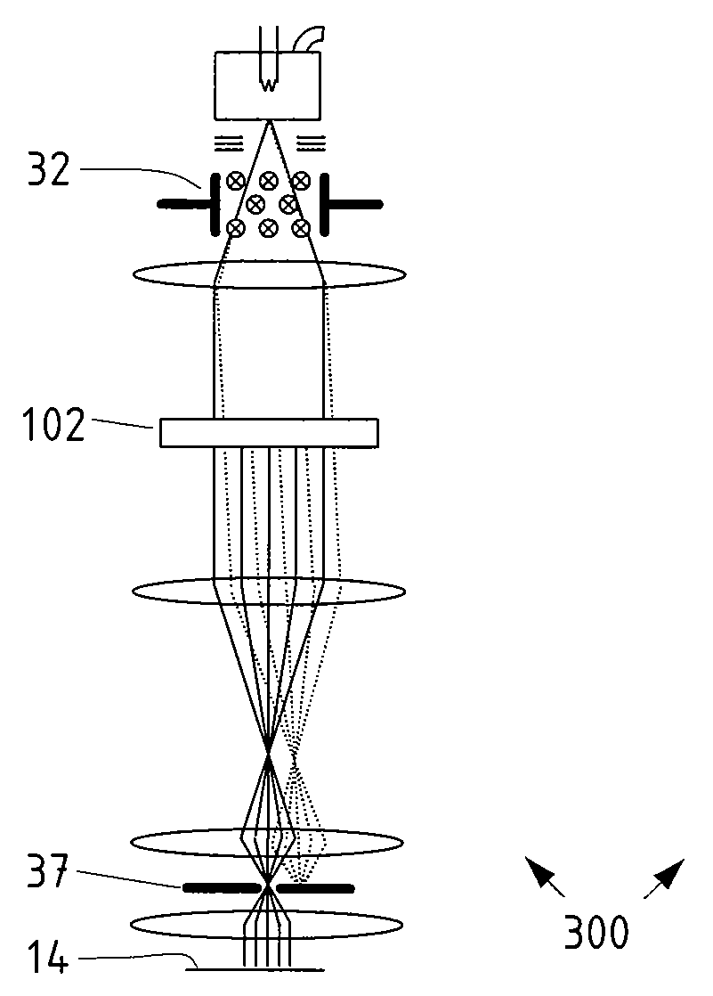
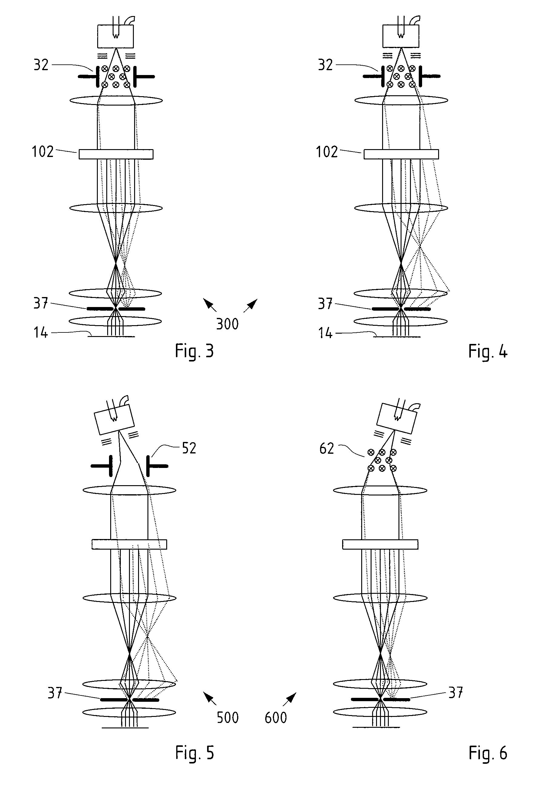
The invention is a modification to a particle filter arrangement that improves its performance by selectively removing unwanted particles while reducing complexity and the susceptibility to external disturbances. The modification involves using a velocity-dependent deflector means to selectively deflect beam particles based on their velocity, with a delimiting means to remove particles that are not in the desired species. This results in a smaller optical column and reduced number of optical elements, as well as reduced energy requirements for the system. The invention also reduces the effect of Coulomb interaction and improves the life time of the delimiting plate. Overall, the invention simplifies the process of selecting desired particle species and improves the overall performance of the particle filter arrangement.

Problems solved by technology

This is particularly important if beams of heavy ions are used, which generally cause significant sputtering.
This comes about since in the state of art devices, an additional crossover is needed in the illumination system and the particle beam energy in the Wien deflector is limited to comparatively low values in order to achieve the required mass and energy resolution.

Method used


Image

  • Particle-beam apparatus with improved wien-type filter
  • Particle-beam apparatus with improved wien-type filter
  • Particle-beam apparatus with improved wien-type filter

Examples


Embodiment Construction

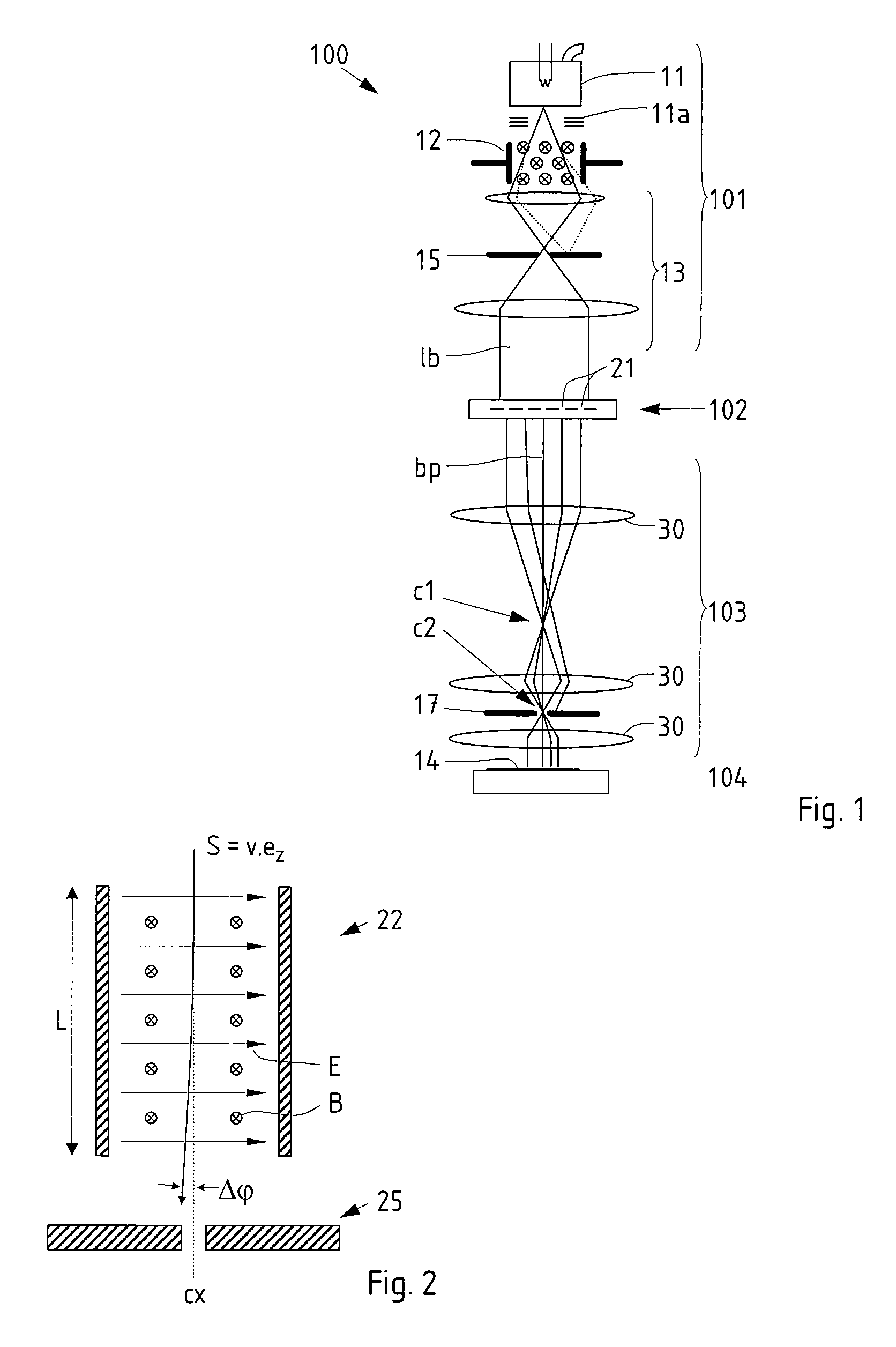
[0031]The preferred embodiment of the invention discussed in the following is based on the PML2-type particle-beam exposure apparatus with a pattern definition (PD) system as disclosed in the U.S. Pat. No. 6,768,125 (=GB 2 389 454 A) of the applicant (assignee), and with a large-reduction projecting system. In the following, first the technical background of the apparatus is discussed as far as relevant to the invention, then embodiments of the invention are discussed in detail. It should be appreciated that the invention is not restricted to the following embodiments nor the PD system, which merely represent one of the possible implementations of the invention; rather, the invention is suitable for other types of processing systems that employ a particle-beam with projection stages as well.

PML2 System

[0032]A schematic overview of a maskless particle-beam processing apparatus PML2 employing the invention is shown in FIG. 1. In the following, only those details are given as needed to...


PUM


Abstract

In a particle-beam apparatus for irradiating a target, a pattern defined in a pattern definer is projected onto the target through a projection system by a beam of energetic electrically charged particles of, largely, a species of a nominal mass having a nominal kinetic energy. To generate the beam, a particle source, a velocity-dependent deflector and an illumination optics system are provided. The velocity-dependent deflector includes a transversal dipole electrical field and / or a transversal dipole magnetic field, which act upon the particles so as to causing a deviation of the path of the particles with regard to the paths of the nominal species which is dependent on the velocity of the particles. A delimiter is provided as a component of the pattern definer or, preferably, the projection system, serving to remove particles whose paths are deviating from the nominal path.

Description

FIELD OF THE INVENTION AND DESCRIPTION OF PRIOR ART[0001]The invention relates to improvements on a particle-beam apparatus for irradiating a target. The apparatus comprises: a particle source adapted to generate a beam of energetic electrically charged particles the majority of which conform to a nominal species of a nominal mass having a nominal kinetic energy, but some of the particles may be impurities; an illumination optics system for forming said beam into an illuminating beam which is substantially tele / homocentric along an optical path; a pattern definition means located after the illumination optics system as seen along the direction of the beam, which comprises a plurality of apertures adapted to form the illuminating beam into a plurality of beamlets; a projection system configured to form the beamlets emerging from the pattern definition means into a final image of the apertures; and a target stage means adapted to position a target at the position of said final image.B...

Claims


Application Information

Patent Timeline
Patent Type & Authority Applications(United States)
IPC IPC(8): H01J3/26
CPCB82Y10/00B82Y40/00H01J2237/057H01J37/3174H01J2237/0435H01J37/05
Inventor PLATZGUMMER, ELMAR
Owner IMS NANOFABTION
Learn More