Method for multilevel programming of phase change memory cells using a percolation algorithm

a phase change memory and percolation algorithm technology, applied in the field of multilevel programming of phase change memory cells and to multilevel phase change memory devices, can solve the problems of rapid resistivity drift, unstable resistivity of amorphous chalcogenic materials, and large amorphous regions still created, and subject to resistivity dri

Active Publication Date: 2008-06-26
MICRON TECH INC
View PDF6 Cites 92 Cited by
  • Summary
  • Abstract
  • Description
  • Claims
  • Application Information

AI Technical Summary

Benefits of technology

[0041]FIG. 8 shows one of the advantages of the present invention. Specifically, the percolation path provides a reduced resistance drift. The percolation path is a parallel current path through the chalcogenic material that effectively hides any series current components. The plot of the drift component for the percolation path is shown with the triangular plot points, whereas a series path, shown by diamonds, has higher resistance drift.

Problems solved by technology

However, the resistivity of the amorphous chalcogenic material is not stable and continuously increases according to a sub-linear law after phase transition.
Thus, a quite rapid resistivity drift may take place, especially when large extensions of chalcogenic material are brought to the amorphous state.
In this manner, however, large amorphous regions are still created, which are subjected to resistivity drift.
Thus, a sense amplifier associated with multilevel cells would fail to distinguish adjacent levels in a relatively short time after each phase transition.
Moreover, the configuration of the large amorphous regions that are every time created greatly affects the resistivity level, but is not predictable.
Thus, repeating identical programming cycles on the same phase memory change cell may lead to different resistivity levels.

Method used


Image

  • Method for multilevel programming of phase change memory cells using a percolation algorithm
  • Method for multilevel programming of phase change memory cells using a percolation algorithm
  • Method for multilevel programming of phase change memory cells using a percolation algorithm

Examples


Embodiment Construction

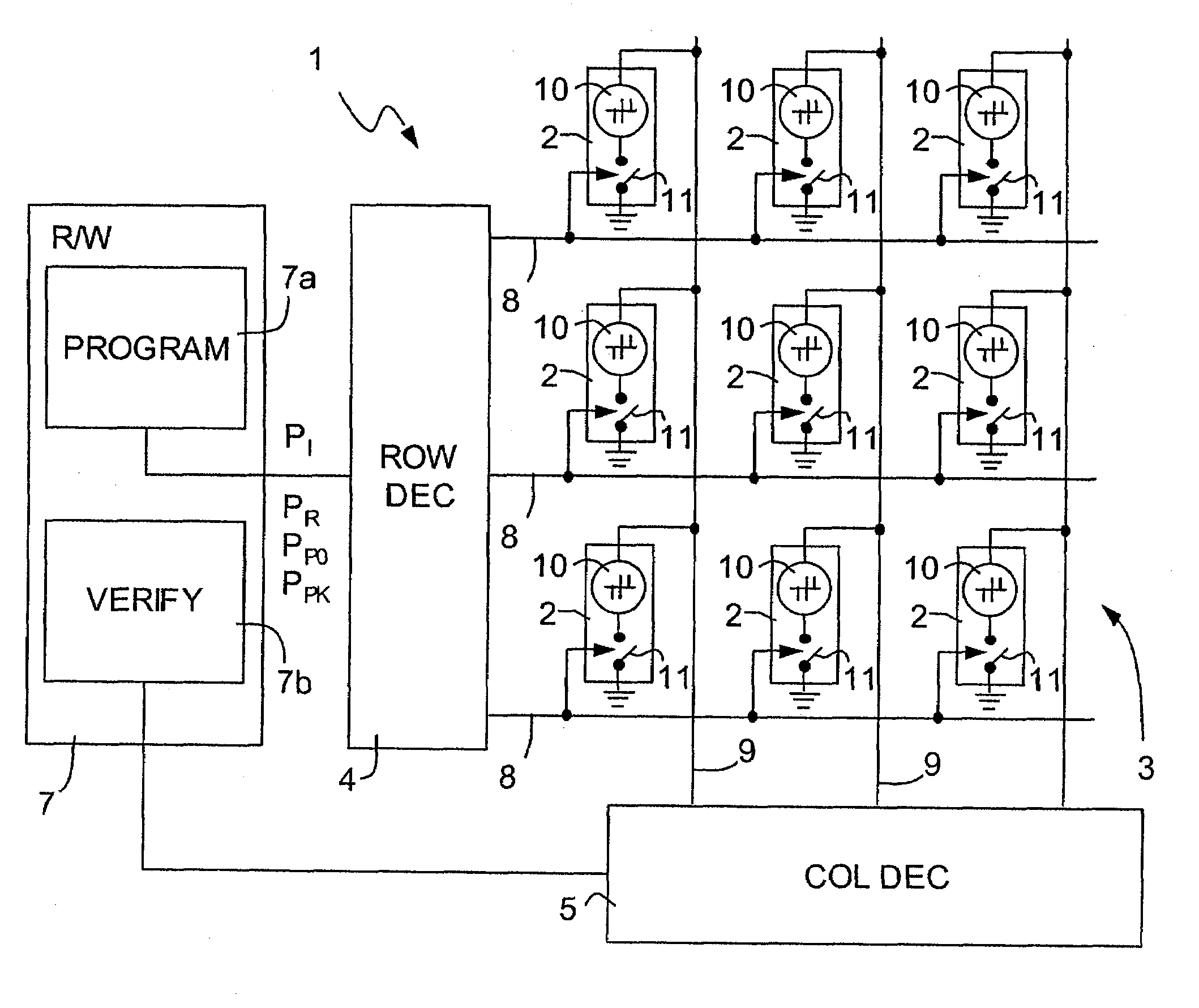
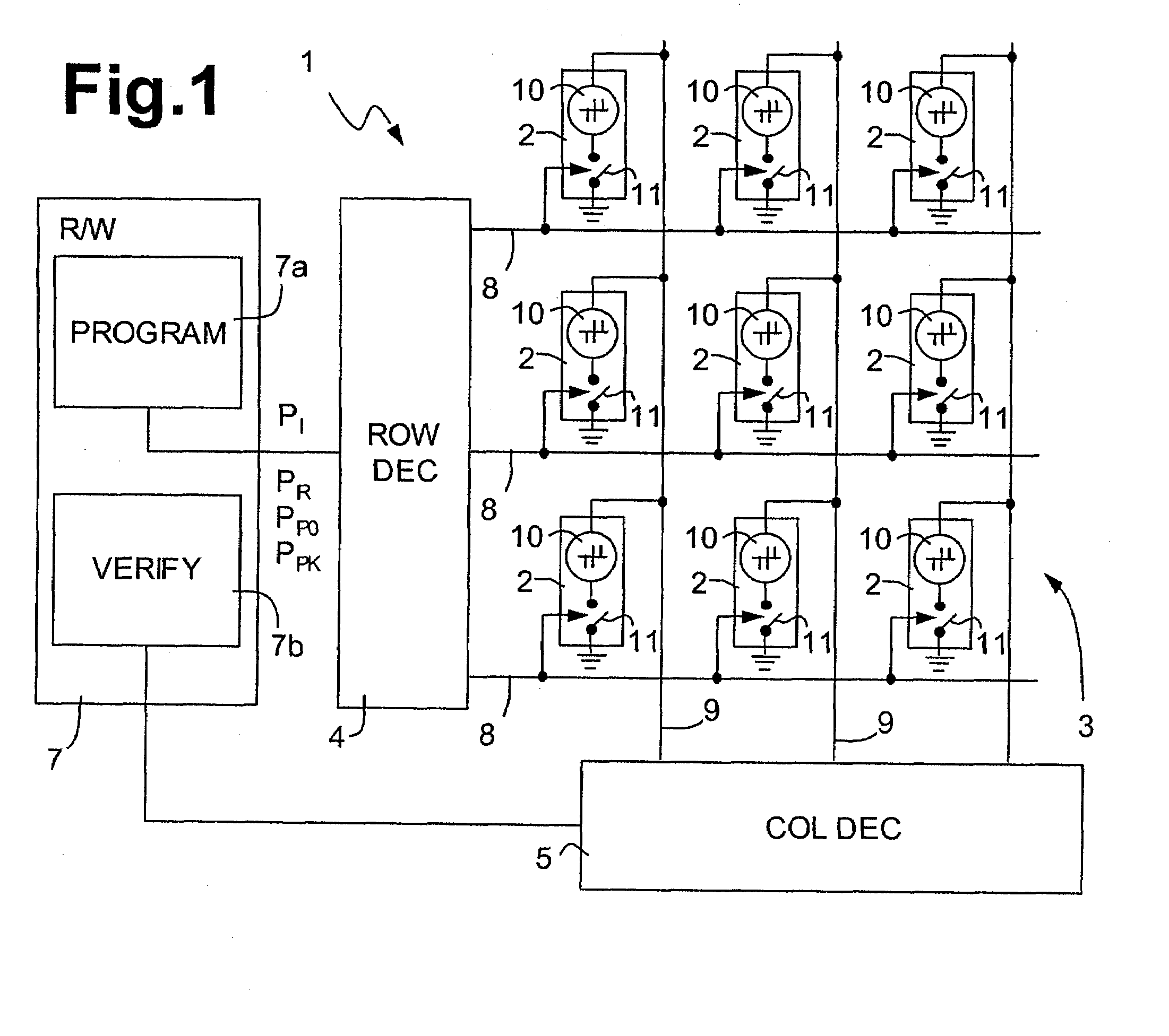
[0030]FIG. 1 shows a phase change memory (“PCM” hereinafter) device 1. A plurality of PCM cells 2 are arranged in rows and columns to form an array 3. A row decoder 4 and a column decoder 5 are coupled to a read / write unit 7, which includes a programming circuit 7a and a verify circuit 7b. Word lines 8 and bit lines 9 run parallel to rows and columns, respectively, and are selectively connectable to the read / write unit 7 through the row decoder 4 and the column decoder 5, in a known manner.

[0031]PCM cells 2 are connected at a cross-point of a word line 8 and a bit line 9 and include a memory element 10, of the phase change type, and a selection element 11. The memory element 10 has a first terminal connected to its respective bit line 9 and a second terminal connected to a first terminal of the selection element 11. The selection element 11 has a second terminal grounded and a control terminal connected to a word line 8. According to alternative solutions, the memory element 10 and ...


PUM


Abstract

A method and apparatus for programming a phase change memory cell is disclosed. A phase change memory cell includes a memory element of a phase change material having a first state, in which the phase change material is crystalline and has a minimum resistance level, a second state in which the phase change material is amorphous and has a maximum resistance level, and a plurality of intermediate states with resistance levels there between. The method includes using programming pulses to program the phase change memory cell in either the set, reset, or one of the intermediate states. To program in the intermediate states, a programming pulse creates a crystalline percolation path having an average diameter through amorphous phase change material and a second programming pulse modifies the diameter of the crystalline percolation path to program the phase change memory cell to the proper current level.

Description

BACKGROUND OF THE INVENTION[0001]1. Field of the Invention[0002]The present invention relates to a method for multilevel programming of phase change memory cells and to a multilevel phase change memory device.[0003]2. Description of the Related Art[0004]As is known, phase change memories use a class of materials that have the property of switching between two phases having distinct electrical characteristics, associated with two different crystallographic structures of the material: an amorphous, disorderly phase, and a crystalline or polycrystalline, orderly phase. The two phases are hence associated to resistivities of considerably different values.[0005]Currently, the alloys of elements of group VI of the periodic table, such as Te or Se, referred to as chalcogenides or chalcogenic materials, can be used advantageously in phase change memory cells. The currently most promising chalcogenide is formed from an alloy of Ge, Sb and Te (Ge2Sb2Te5), which is now widely used for storing ...

Claims


Application Information

Patent Timeline
Patent Type & Authority Applications(United States)
IPC IPC(8): G11C7/00G11C11/00
CPCG11C11/5678G11C13/0004G11C13/004G11C13/0064G11C2213/79G11C2013/0054G11C2013/0078G11C2013/0083G11C2013/009G11C13/0069G11C16/10
Inventor PELLIZZER, FABIOPIROVANO, AGOSTINO
Owner MICRON TECH INC
Why Eureka
Try Eureka