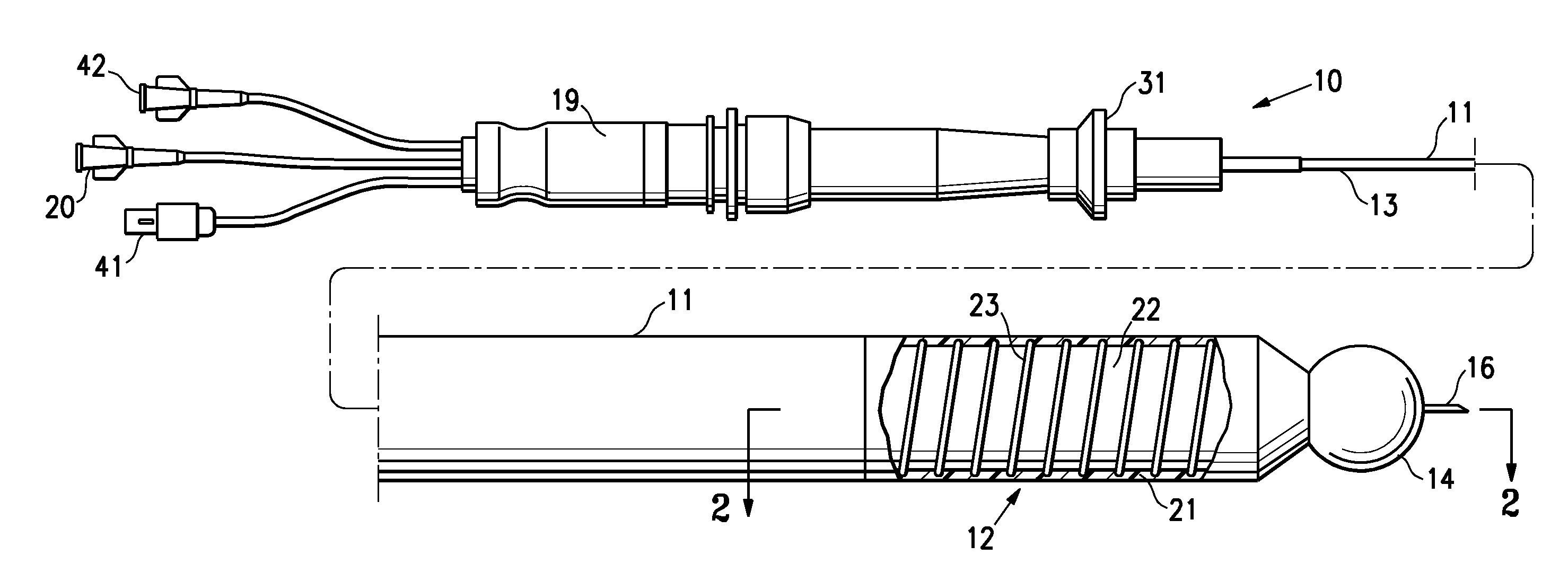
[0005]The invention is directed to a catheter for use in a patient's body lumen, having a shaft section configured to minimize ultrasonic image artifacts and the direct ultrasonic image brightness of the shaft surface and its internal components, and to produce its image (i.e., appear) at a wide range of imaging angles, preferably with an intensity not substantially different than surrounding tissue of the patient's body lumen under ultrasound
visualization. The shaft section is operative for the desired use of the catheter, yet is also configured to facilitate accurately imaging the shape and location of the shaft section, and easily differentiate it from the surrounding
anatomy, without unduly obscuring the images of the adjacent anatomy, using an
ultrasound imaging system.
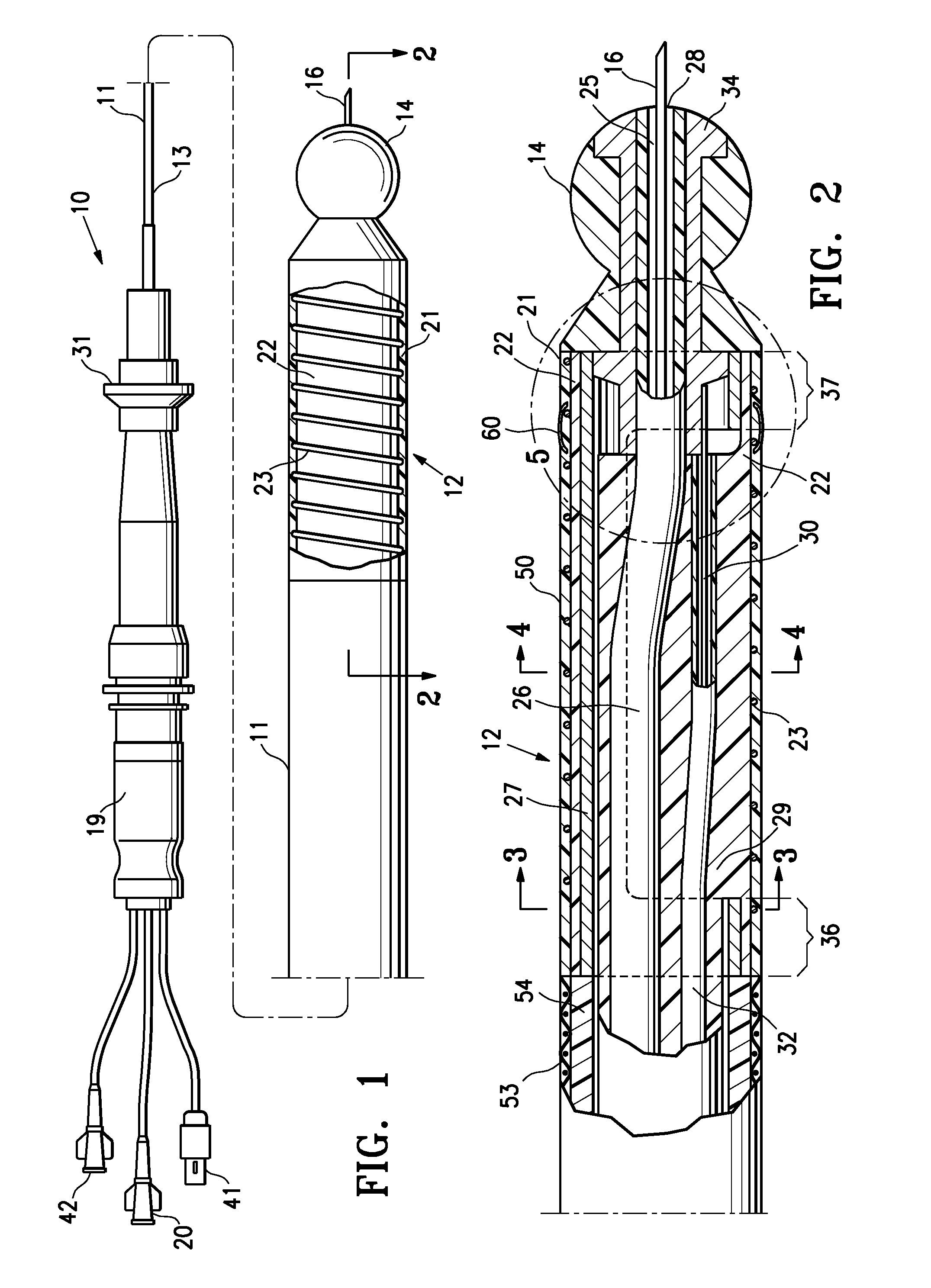
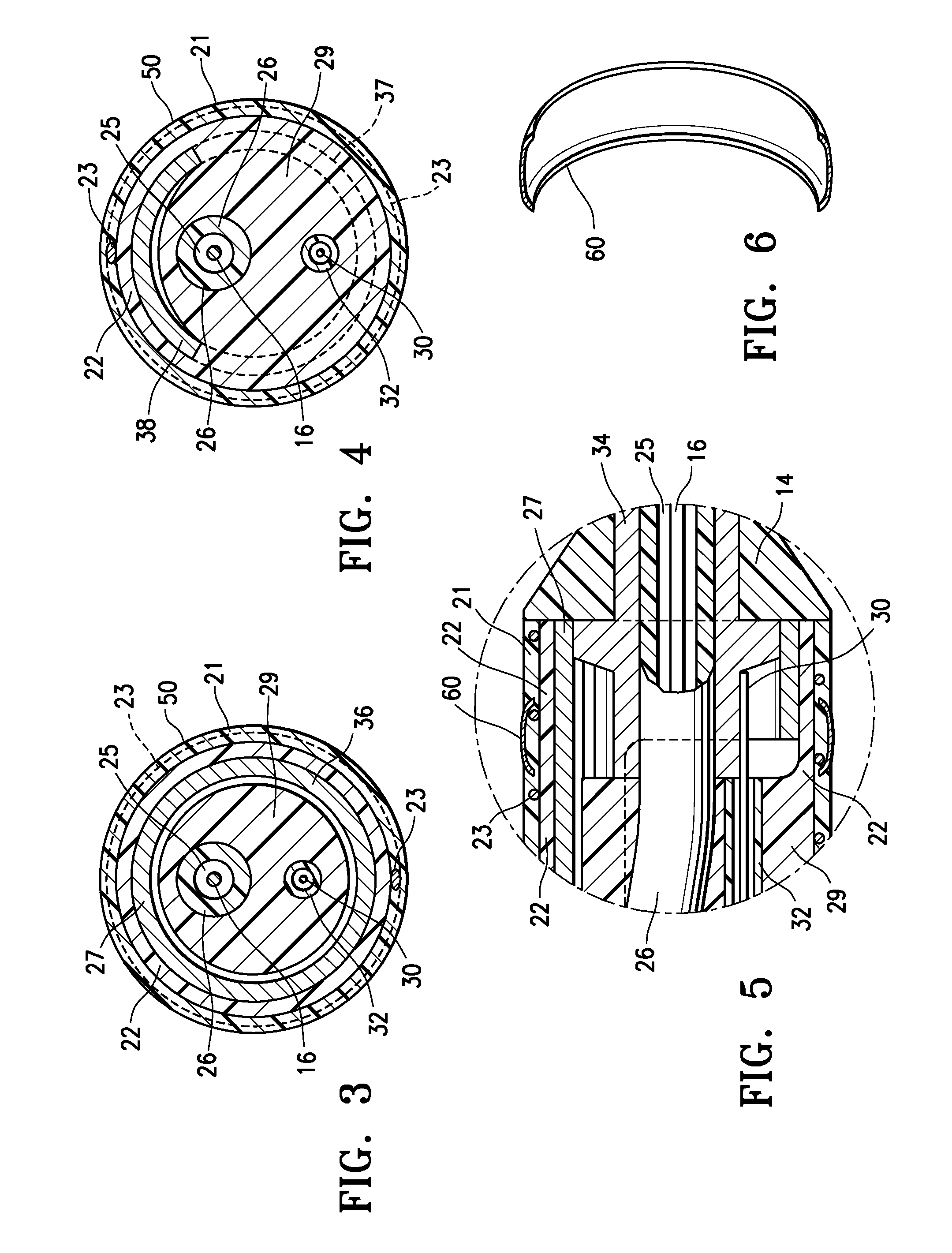
[0009]The echogenic member is preferably a rounded or curved member or members extending helically along or circumferentially around the distal shaft section, such as a round
metal wire(s) coiled around the shaft section. The echogenic member is preferably located between the two echo diffusive and dampening
layers, and is configured at least in part with a curved surface to diffusely reflect a portion of the incident sonic energy back to the
transducer of the
ultrasonic imaging system at a wide range of incident angles to produce a shaft image with a brightness near that of the adjacent tissues irrespective of the imaging angle (direct or oblique). Although discussed primarily in terms of a coiled
metal wire member, other, less easily mounted (and thus less preferred), configurations such as a series of rings or beads with a curved outer surface and mounted circumferentially at intervals along the length of the shaft section can alternatively be used as the echogenic member having a variety of suitable cross sectional shapes. In a presently preferred embodiment, the echogenic member is comprised at least in part of a
metal or a blend /
alloy containing a metal or metals. It should be understood that the echogenic member is a different member than the metallic member(s) of the distal shaft section having the echo diffusive and dampening
layers thereon. A metal bearing echogenic member allows the echogenic member to be thin and thus to not substantially increase the outer
diameter of the shaft section. This is preferred at least in part because smaller
diameter shafts have fewer
insertion site complications. In a presently preferred embodiment, the distal shaft section has a substantially smooth outer surface. In other embodiments, the echogenic member causes a small raised surface at the outer
diameter of the shaft.
[0010]In one embodiment, the shaft distal section has an
electrode, or other sensing or transmitting component (e.g., a
transducer, electrical sensor,
fiber optic sensor), imbedded or in contact with at least the echo diffusive and dampening outer layer, and one aspect of the invention is directed to configuring the sensing or transmitting component to minimize its echo amplitudes and artifacts while having a brightness that facilitates ultrasonic
visualization of its position on the shaft, and to diffusely reflect a portion of the incident sonic energy back to the
transducer / probe of the
ultrasonic imaging system at a wide range of incident angles to facilitate its ultrasonic visualization at a wide range of imaging angles (sonic energy incident angles). In embodiments in which the sensing / transmitting component (e.g.,
electrode) is mounted on the deflectable distal shaft section, it should be understood that the section of the shaft that is rendered substantially echolucent by the echo diffusive and dampening layers is the rest of the deflectable distal section not having the sensing / transmitting component mounted thereto. In a presently preferred embodiment, the sensing / transmitting component is connected to the echogenic member. In this embodiment, the echogenic member is a conductor or
optical fiber assembly and may extend to the proximal portion of the catheter to function as an electrical and / or
fiber optic cable to a catheter connector or be operatively connected to such a cable. Although discussed primarily in terms of providing the
electrical connection for an
electrode, it should be understood that the echogenic member may act as the cable for a variety of transducers and / or sensors mounted on the shaft in other embodiments.
[0013]The deflectable distal shaft section having the coiled metal wire member or other echogenic member(s) between the two echo diffusive and dampening layers is preferably configured to produce a shaft image that is substantially the same brightness as the images simultaneously produced of the surrounding tissue of the patient's body lumen, and that is at or nearly at the shaft's actual location in the anatomy, and with echo amplitudes and timing that produce a shaft image size / width that is substantially equal to the shaft's actual size with the
gain of the ultrasonic imaging system set to optimally image the patient's heart or other adjacent anatomy. For use with two-dimensional (2D) ultrasonic imaging systems, the deflectable distal shaft section is preferably configured to produce a shaft image that is a continuous (i.e., an elongated tubular shape) shaft image. In contrast, for three-dimensional (3D) imaging applications, it is preferred that it produces a discontinuous shaft image (e.g., a series of short
diagonal lines, a dashed line and / or a dotted line). In two-dimensional imaging applications, a discontinuous image can result in displayed images that lack a discernable image of the shaft and therefore, a discontinuous image is not preferred. However, in three-dimensional imaging applications, a discontinuous shaft image is displayed in the imaging volume as a series of short
diagonal lines, a dashed line and / or a dotted line in the most useful three-dimensional
image display formats (for example, see through formats and surface formats). In three-dimensional
image display formats, a discontinuous shaft image is so different from the anatomy image that the shaft image is very easily differentiated from the adjacent anatomy and therefore, a discontinuous shaft image for at least a portion of the shaft is preferred. Additionally, the discontinuous shaft image has a number of advantages including allowing the physician to count the number of discontinuous segments of the echogenic member which are currently visible on the image monitor in order to gauge sizes or distances in the patient's anatomy, or in order to determine whether the key part of the catheter is included in the image. For example, if the discontinuous image portion of the catheter is located at or near to its distal tip or work element, then counting the number of visible discontinuous segments of the echogenic member in comparison to the known total number will assure that the distal tip or work element is in the image. Variations in the discontinuous shaft image segments can also be exploited to help differentiate different regions of the shaft.
[0016]A catheter of the invention results in an image of at least a portion of the catheter on an
ultrasound imaging system's display that is substantially free of the usual shaft image artifacts that falsely represent the shaft's location and that obscure adjacent tissue images with large and very bright images. The catheter has at least a shaft section that produces a shaft image with a brightness / intensity similar to that of the tissue of the surrounding anatomy, and with a size (diameter) substantially similar to the shaft's actual size. Additionally, the catheter shaft produces this image from a wide range of imaging angles. The produced shaft section image may be a continuous image, a discontinuous image, or contain one or more continuous and discontinuous image sections, as preferred for the
image display format and the portions of interest of the shaft. Moreover, in addition to improving the visualization of the catheter under ultrasonic imaging, the catheter shaft is configured to facilitate the atraumatic advancing, maneuvering, and positioning the operative distal end at a desired location in the patient's body lumen to perform a
medical procedure. These and other advantages of the invention will become more apparent from the following Detailed Description and accompanying exemplary drawings.

