Method for estimating parameters of a navigation signal

a navigation signal and parameter estimation technology, applied in direction finders, navigation instruments, instruments using radio waves, etc., can solve the problems of inability to consider, increase the probability of losing lock, and errors in position estimation, so as to improve performance, reduce spacing, and estimate delay better

Inactive Publication Date: 2008-06-26
DEUTSCHES ZENTRUM FUER LUFT & RAUMFAHRT EV
View PDF12 Cites 4 Cited by
  • Summary
  • Abstract
  • Description
  • Claims
  • Application Information

AI Technical Summary

Benefits of technology

[0010]The estimation errors of the DLL and PLL are considered to be Gaussian today, such that the associated likelihood function for the estimates is consequently also a Gaussian. Actually the likelihood function is not a Gaussian and the conventional approach is not able to consider this.
[0011]In addition the DLL adjusts the derivative of the correlation function such that it becomes zero. This method is suboptimal due to the approximation of the derivative and it is known that the delay can be estimated better, if the approximation becomes more accurate. Practically this is achieved by decreasing the correlator spacing A, which yields improved performance with respect to the estimation error for the delay. Anyhow decreased spacing A deteriorates the dynamic performance of the DLL and leads to an increased probability of loosing lock, such that a trade-off between the different performance criteria is required.
[0019]predicting the complex amplitude and time delays by performing equivalent time delay shifts and phase s...

Problems solved by technology

A major problem for the TOA method are errors of the respective delay and phase estimates, which result in errors of the position estimate.
Disadvantages of State of the Art Approach
Actually the likelihood function is not a Gaussian and the conven...

Method used


Image

  • Method for estimating parameters of a navigation signal
  • Method for estimating parameters of a navigation signal
  • Method for estimating parameters of a navigation signal

Examples


Embodiment Construction

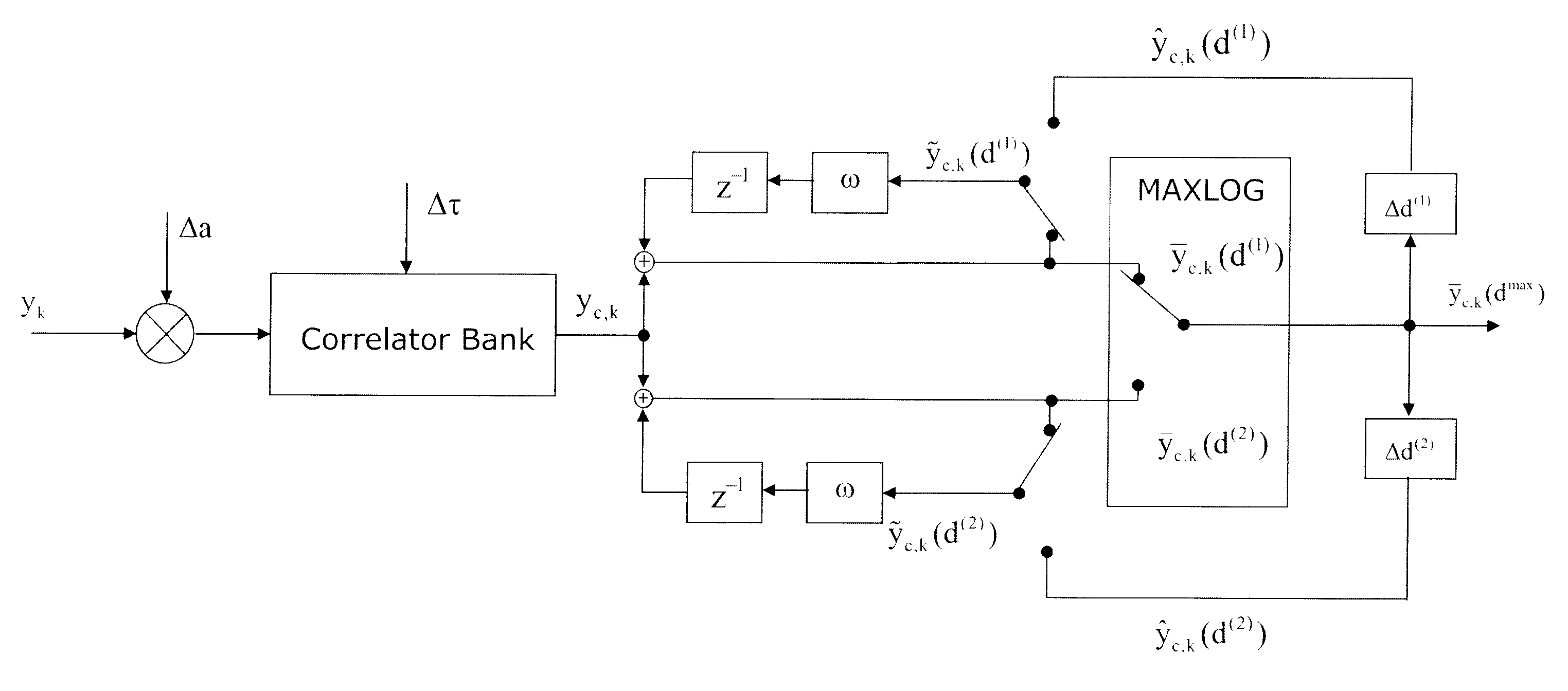
[0038]In particular high complexity arises from the evaluation of the likelihood, which requires operations upon a data set of many thousand samples for each code period of the received signal. Thus, within conventional navigation receivers tracking loops are used for estimating the signal parameters. It can be shown that signal compression techniques can overcome the problem of computational complexity, as the likelihood function can be formulated efficiently upon a reduced data set of much smaller size compared to the original data, where the reduced data set forms a sufficient statistic for the estimated signal parameters. As a consequence the evaluation of the likelihood becomes feasible with moderate cost, which allows an improved information hand over from the signal parameter estimation part to the navigational part of the receiver. Within this paper a novel approach for integrating a conventional tracking loop with a likelihood evaluator is proposed. It is shown that for the...


PUM


Abstract

The method for estimating parameters of a navigation signal received by a receiver which receives navigation signals through a plurality of paths wherein the parameters include data modulated on the navigation signal and complex amplitudes i.e. amplitude and phase shift, and time delays of the individual paths, comprises receiving a navigation signal and sampling the received navigation signal. Moreover, the parameters are sequentially estimated in terms of a posterior probability density function. For facilitating the sequential estimation, the received vector is transformed into a compressed vector without loss of information by using a correlator bank having a plurality of correlator reference signals. The sets of samples representing the posterior probability function of the parameters are sequentially calculated by nonlinearly, recursively filtering the compressed vector and optionally predicting the complex amplitude and time delays by performing equivalent time delay shifts and phase shifts of the correlator signals of the correlator bank.

Description

BACKGROUND OF THE INVENTION[0001]1. Field of the Invention[0002]The present invention relates to a method for estimating parameters of a navigation signal which is received by a receiver which receives navigation signals through a plurality of paths wherein the parameters include data modulated on the navigation signal and complex amplitudes, e.g. amplitude and phase shift, and time delays of the individual paths.[0003]2. Description of the Prior Art[0004]Estimation of signal parameters (in particular delay and phase) of signals, which are transmitted by signal transmitters of known position to the receiver allow for position determination of the receiver within the three-dimensional space, insofar as within a synchronous system wherein the receiver clock is synchronized to the clocks of the transmit stations at least the signals of three transmitting station can be received. When the receiver clock is not synchronized to the clocks of the transmit stations, it is required to receiv...

Claims


Application Information

Patent Timeline
IPC IPC(8): G01C21/00
CPCG01S19/22
Inventor KRACH, BERNHARDLENTMAIER, MICHAEL
Owner DEUTSCHES ZENTRUM FUER LUFT & RAUMFAHRT EV
Why Eureka
Try Eureka