

Polarizing plate and liquid crystal display device
a liquid crystal display device and polarizing plate technology, applied in the direction of optical elements, instruments, transportation and packaging, etc., can solve the problem of frame-like light leakage, and achieve the effect of high-durability polarization and less causative of light leakag
- Summary
- Abstract
- Description
- Claims
- Application Information
AI Technical Summary
Benefits of technology
Problems solved by technology
Method used
Image

Examples
example 1
Production of Cellulose Acetate Film
[0191]The composition below was placed in a mixing tank, and stirred under heating to dissolve the individual ingredients, to thereby prepare a cellulose acetate solution.
Cellulose acetate, degree of acetylation 60.9%100 parts by massTriphenyl phosphate (plasticizer) 7.9 parts by massBiphenyldiphenyl phosphate (plasticizer) 3.9 parts by massMethylene chloride (first solvent)245 parts by massMethanol (second solvent) 20 parts by mass
[0192]In another mixing tank, 16 parts by mass of retardation enhancer shown below, 80 parts by mass of methylene chloride and 20 parts by mass of methanol were placed, and stirred under heating to thereby prepare a retardation enhancer solution. To 477 parts by mass of the cellulose acetate solution, 22 parts by mass of the retardation enhancer solution was mixed, and thoroughly mixed to prepare a dope. Amount of addition of the retardation enhancer was 3.0 parts by mass per 100 parts by mass of cellulose acetate.
[0193...
example 2
Production of Cellulose Acetate Film
[0205]The composition below was placed in a mixing tank, and stirred under heating to dissolve the individual ingredients, to thereby prepare a cellulose acetate solution.
Cellulose acetate having a degree of acetylation 60.9%100 parts by massTriphenyl phosphate (plasticizer) 3.7 parts by massBiphenyldiphenyl phosphate (plasticizer) 2.0 parts by massMethylene chloride (first solvent)250 parts by massMethanol (second solvent) 20 parts by mass
[0206]In another mixing tank, 16 parts by mass of retardation enhancer used in Example 1, 80 parts by mass of methylene chloride, and 20 parts by mass of methanol were placed, and stirred under heating to thereby prepare a retardation enhancer solution. To 477 parts by mass of the cellulose acetate solution, 22 parts by mass of the retardation enhancer solution was mixed, and thoroughly mixed to prepare a dope. Amount of addition of the retardation enhancer was 3.0 parts by mass per 100 parts by mass of cellulos...
example 3
Preparation of Pressure-Sensitive Adhesive Syrup
[0214]A pressure-sensitive adhesive syrup was then prepared by dissolving 60 parts by mass of NR (pale crepe), 40 parts by mass of SBR (B / S=71 / 29), 10 parts by mass of polyisobutylene, 60 parts by mass of polyterpene resin (softening point=115° C.), 10 parts by mass of hydrogenated rosin glycerol ester, and 2 parts by mass of antioxidant (2,6-di-t-butyl-4-cresol) into n-hexane so as to adjust the solid content to 20%.
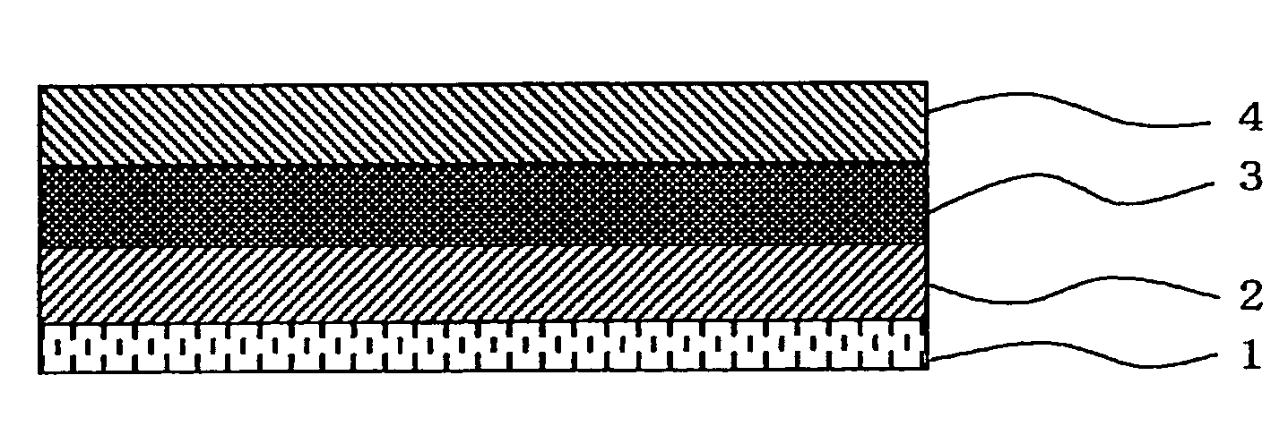
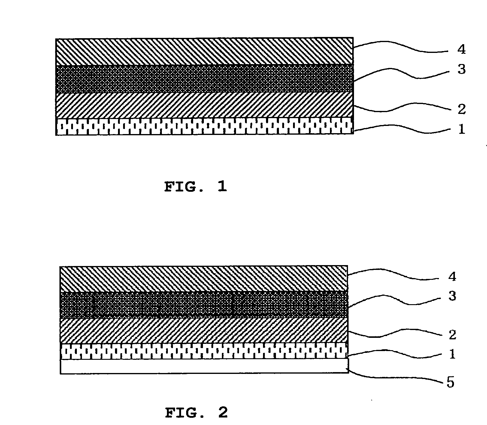
[0215]The polarizing plate configured similarly to as shown in FIG. 2 was produced in the same manner as Example 1, except that the pressure-sensitive adhesive layer was formed using the pressure-sensitive adhesive syrup prepared in the above.
[0216]Photoelastic coefficient of the resultant pressure-sensitive adhesive layer measured by the ellipsometer (M-150, from JASCO Corporation) was found to be 100×10−12 (1 / Pa).
[0217]Y value of the polarizing plate was consequently found to be 2.6×10⁻⁴
(Evaluation)
[0218]Two polarizing ...
PUM
| Property | Measurement | Unit |
|---|---|---|
| Fraction | aaaaa | aaaaa |
| Fraction | aaaaa | aaaaa |
| Angle | aaaaa | aaaaa |
Abstract
Description
Claims
Application Information