
Receiver circuit and receiving method

a receiver circuit and receiver technology, applied in the field of receiver circuits, can solve problems such as serious problems in cellular phone terminals and undesirable increase in the size of the s

Inactive Publication Date: 2008-07-03
ROHM CO LTD
View PDF3 Cites 39 Cited by
  • Summary
  • Abstract
  • Description
  • Claims
  • Application Information

AI Technical Summary

Benefits of technology

[0017]Such an embodiment allows the serial data output from the baseband circuit to be reproduced in a sure manner.

Problems solved by technology

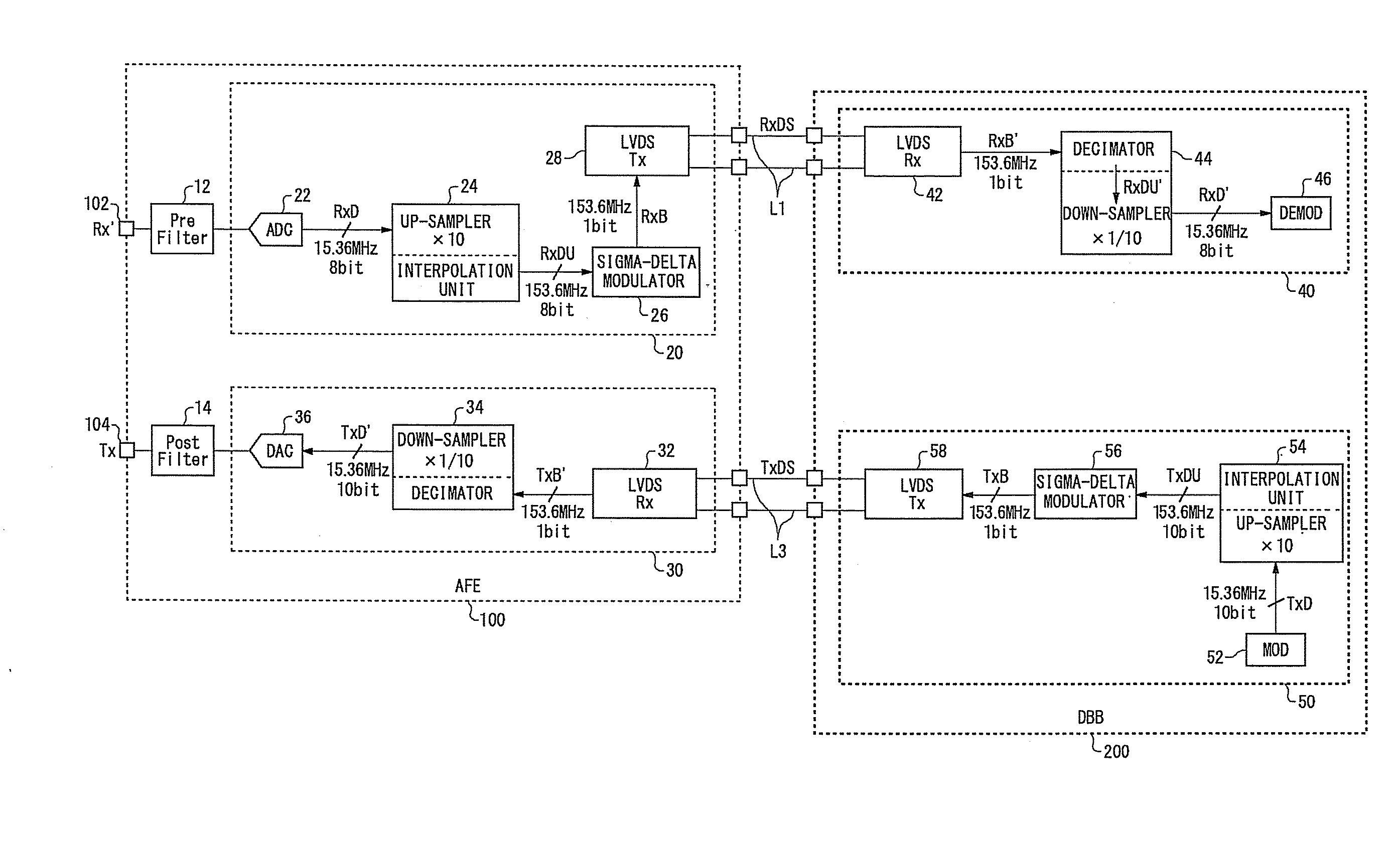
Accordingly, such an increase in the signal lines leads to a serious problem in cellular phone terminals.
Such additional signal lines lead to an undesirable increase in the size of the set.

Method used


Image

  • Receiver circuit and receiving method
  • Receiver circuit and receiving method
  • Receiver circuit and receiving method

Examples


Embodiment Construction

[Best Mode for Carrying Out the Invention]

[0027]The invention will now be described based on preferred embodiments which do not intend to limit the scope of the present invention but exemplify the invention. All of the features and the combinations thereof described in the embodiment are not necessarily essential to the invention.

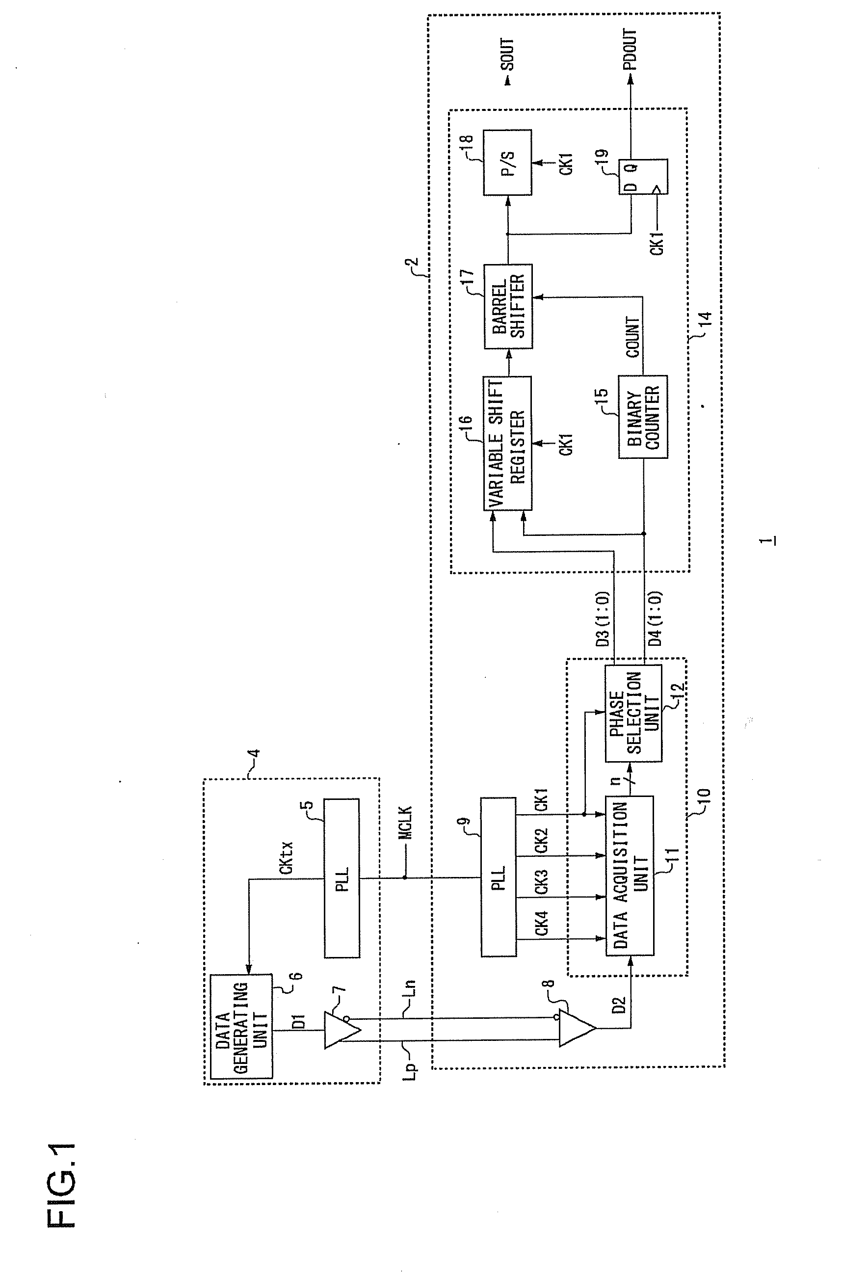
[0028]FIG. 1 is a block diagram which shows an overall configuration of a transmission / reception system 1 according to the present embodiment. The transmission / reception system 1 includes a receiver circuit 2 and a transmission circuit 4. In the circuit shown in FIG. 1, the receiver circuit 2 and the transmission circuit 4 perform transmission / reception of data via differential signal lines Lp and Ln using differential signals such as an LVDS (Low Voltage Differential Signal). It should be noted that the transmission method for providing communication between the receiver circuit 2 and the transmission circuit 4 is not restricted to the aforementioned diffe...


PUM


Abstract

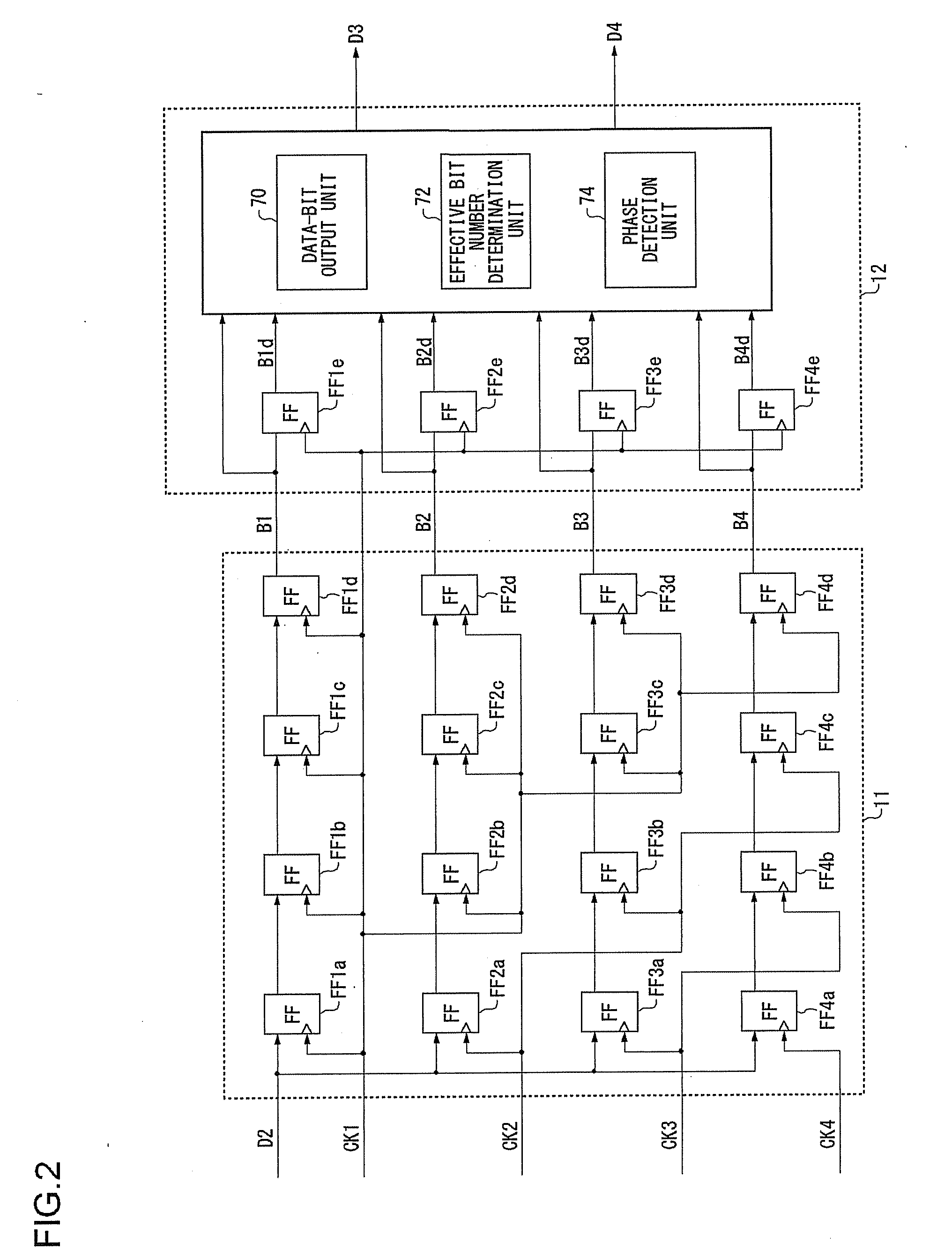
Clock signals are supplied, with a phase shift of 1 / n cycles between adjacent clock signals. A data acquisition unit acquires serial data at a timing of each of the clock signals. A phase detection unit detects the phase of the transition edge of the serial data using n bits of data. An effective bit number determination unit determines the effective bit number, which is the number of bits to be acquired, based upon the phase of the transition edge of the serial data in the current data-bit acquisition step and the phase of the transition edge of the serial data in the previous data-bit acquisition step. A data-bit output unit outputs the effective bit number of the bits of data acquired at a timing of each clock signal having a predetermined phase relation with the transition edge of the serial data.

Description

BACKGROUND OF THE INVENTION[0001]1. Field of the Invention[0002]The present invention relates to a receiver circuit which receives serial data.[0003]2. Description of the Related Art[0004]In recent years, third generation cellular phone communication methods such as CDMA2000 (Code Division Multiple Access), W-CDMA (Wideband-CDMA), etc., have entered the mainstream. These communication methods provide communication at a remarkably high chip rate (or bit rate) as compared with second generation communication methods such as the GSM (Global System for Mobile communication) method, the PDC (Personal Digital Cellular) method, etc.[0005]For example, the W-CDMA method, which is a third generation cellular phone communication method, requires transmission / reception of I / Q signals with a transmission data length of 10 bits and a reception data length of 8 bits between a digital baseband circuit (which will also be referred to simply as a “baseband circuit” hereafter) and an analog wireless c...

Claims


Application Information

Patent Timeline
IPC IPC(8): H04L27/00
CPCH04L7/0338H03M9/00
Inventor TERADA, MAKOTO
Owner ROHM CO LTD
Learn More