
Control system for a vessel with a gyrostabilization system

a control system and gyrostabilization technology, applied in the direction of electric devices, process and machine control, instruments, etc., can solve the problems of people and animals experiencing motion sickness, inefficient at low speeds, and prior gyroscope-related anti-rolling systems that are too large for relatively small vessels

Inactive Publication Date: 2008-07-10
MARINE MOTION CONTROL
View PDF29 Cites 15 Cited by
  • Summary
  • Abstract
  • Description
  • Claims
  • Application Information

AI Technical Summary

Benefits of technology

"The present invention is a control system for a vessel that can bring about desired changes in its dynamic state. The system uses a gyrostabilizer system and other potential actuator systems to control the vessel's roll axis. The system measures key vessel state variables and uses these measurements to determine the correct control commands. The control system can operate in different modes based on the vessel's speed and the type of interaction with the water. The technical effect of the invention is to provide a more effective control system for a vessel that can bring about desired changes in its dynamic state."

Problems solved by technology

A rolling boat is uncomfortable and can cause people and animals to experience motion sickness.
The difficulty with creating such a device is that a boat is not resting on or in a solid medium that can be used as a base to create an anti-rolling moment.
Although the device performed as expected, the Navy stopped installing gyrostabilizers at the onset of WW I. Some gyrostabilizers were installed on private yachts in the first part of the 20th century, but other methods of stabilization supplanted gyrostabilizers in the yacht market.
Fins, interceptors, and foils all depend on significant forward motion for their anti-roll forces, and are inefficient at low speeds.
Prior gyroscope-related anti-rolling systems have either been too massive for relatively smaller vessels, such as yachts, or have been confined to use as a sensing system in combination with a structural element or elements that actually do the stabilizing.
They are less effective in controlling roll motion because the roll moment arm for an individual tab is rather short.
An interceptor creates a disturbance in the flow of water off of the transom, and that disturbance results in a vertical force that is applied to the hull bottom slightly forward of the interceptor.

Method used


Image

  • Control system for a vessel with a gyrostabilization system
  • Control system for a vessel with a gyrostabilization system
  • Control system for a vessel with a gyrostabilization system

Examples


Embodiment Construction

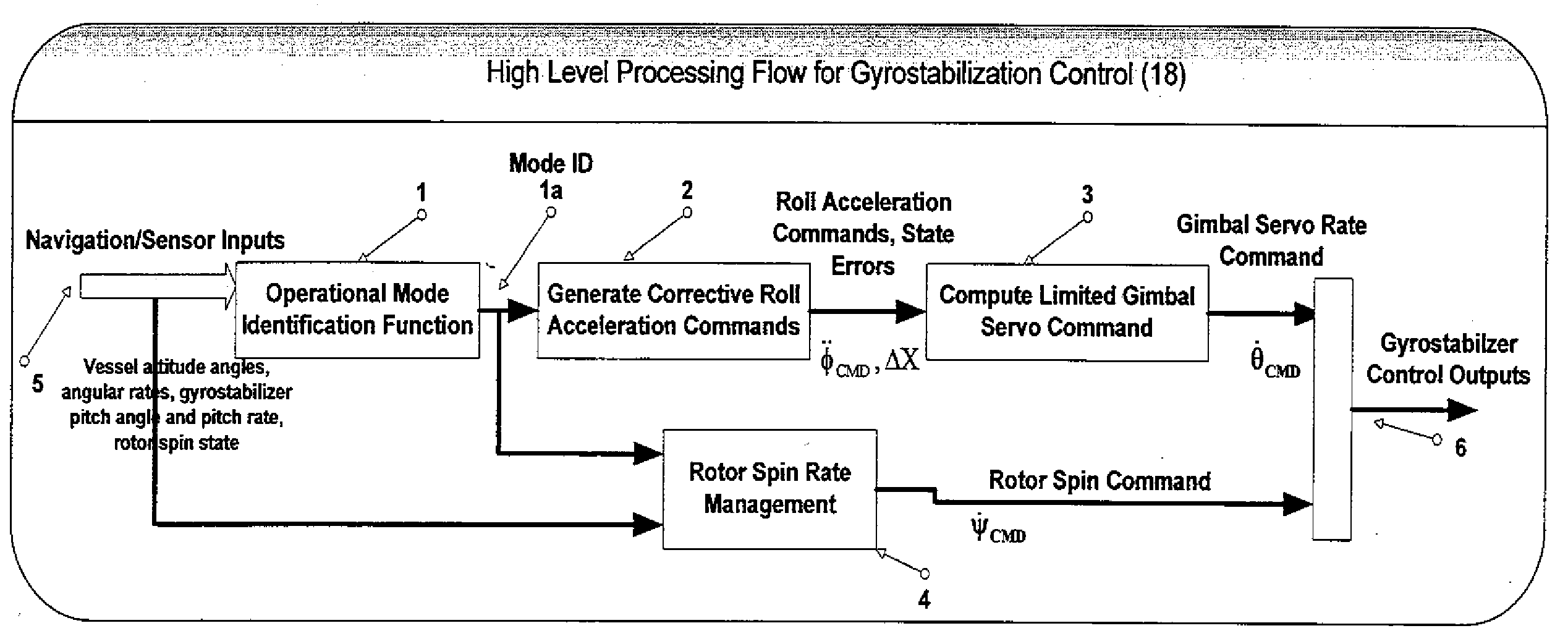
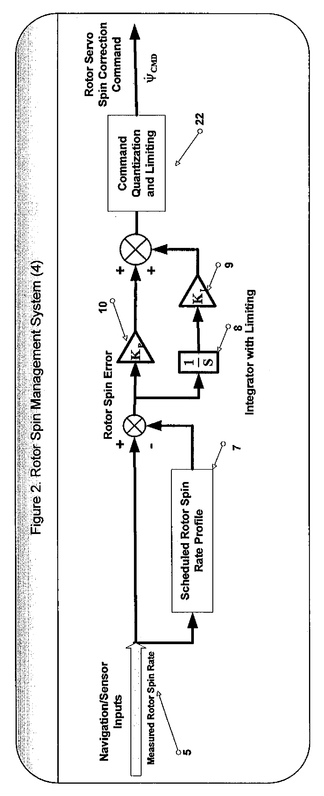
[0041]A high-level process flow for the general control system architecture is shown in FIG. (1). A navigation function (described briefly below) is responsible for the processing of raw sensor data and producing measurements (or mathematically optimal estimates from a navigation filter) of key vessel states such as attitude angles, attitude (angular) rates and possibly velocity. Also, sensors on the gyrostabilizer system may provide feedback of sensed gimbal pitch angle and pitch rate as well as rotor spin rate.

Basic Navigation / Sensor System Requirements

[0042]The goal of the navigation function is to provide the controller with all required state information. This may include (but not be limited to) vessel inertial attitude, angular (attitude) rates in roll, pitch and yaw, vehicle velocity vector, vehicle position vector and depth measurements. Also, sensors can be employed to provide feedback on the gyrostabilizer rotor rate, gimbal pitch angle, gimbal pitch rate and gimbal motor ...


PUM


Abstract

A control system architecture and algorithm to manage a gyrostabilization system for a marine craft. The control system may manage other effectors in addition to the gyrostabilization system. The objective of the control system software is to utilize any and all available control authority so as to bring about the desired change in the vessel's dynamic state. This control authority is produced by the gyrostabilization system or a combination of the gyrostabilization system with a number of other potential actuation systems or effectors. The focus of the gyrostabilizer control portion is the control and stabilization of the vessel's roll axis in particular

Description

CROSS REFERENCE TO RELATED APPLICATION[0001]The present application is a continuation-in-part of, and claims priority benefit in, U.S. nonprovisional application Ser. No. 10 / 958,562, filed Oct. 4, 2004, entitled “GYROSTABILIZER FOR SMALL BOATS” in the name of co-inventor Richard H. Akers, which application claimed the priority benefit of U.S. provisional patent application Ser. No. 60 / 509,653, filed Oct. 8, 2003, entitled “GYROSTABILIZER FOR SMALL BOATS”. The entire contents of both applications are incorporated herein by reference.BACKGROUND OF THE INVENTION[0002]1. Field of the Invention[0003]The present invention relates to systems and devices for stabilizing boats and small ships. More particularly, the present invention relates to control systems for gyroscopic stabilizers and other types of stabilizers positioned in and / or on boats and configured to counteract rolling motion caused by waves and ship wakes.[0004]2. Description of the Prior Art[0005]A rolling boat is uncomfortab...

Claims


Application Information

Patent Timeline
Patent Type & Authority Applications(United States)
IPC IPC(8): G05D1/08
CPCB63B39/04
Inventor RUBENSTEIN, DAVID S.AKERS, RICHARD H.
Owner MARINE MOTION CONTROL
Learn More