
Deep water riser buoyance block closed-loop control system

A deepwater riser and closed-loop control technology, which is applied in the automatic control system of drilling, drilling equipment, and mineral mining, etc., can solve the problems of increasing the accumulation of fatigue damage of the riser, large deformation of the riser, and the decrease of strength and buoyancy efficiency. Reduce water flow excitation and eddy current induced vibration, relieve stress concentration effect, and reduce dynamic damage

Inactive Publication Date: 2009-08-19
SOUTHWEST PETROLEUM UNIV
View PDF0 Cites 12 Cited by
  • Summary
  • Abstract
  • Description
  • Claims
  • Application Information

AI Technical Summary

Problems solved by technology

Documents API RP 16Q, IADC / SPE 103338 disclose two kinds of buoyancy blocks currently used: hollow microsphere foam (syntactic foam) and air tank (aircan / chamber), both of which are circular in shape, and the disadvantage is that the two The buoyancy block will lose buoyancy efficiency due to water infiltration under the action of high hydrostatic pressure for a long time; excessive wave load will cause large deformation of the riser, uneven loading of the top tensioner, and the angle of the bottom ball joint exceeds the normal working limit; excessive eddy current Induced Vibration Increases Fatigue Damage Accumulation of Riser
Synthetic foam is often used as a buoyancy block to reduce the elongation of the upper part of the riser. Its strength and buoyancy efficiency decrease with the increase of water depth; Provides variable buoyancy

Method used


Image

  • Deep water riser buoyance block closed-loop control system
  • Deep water riser buoyance block closed-loop control system
  • Deep water riser buoyance block closed-loop control system

Examples


Embodiment Construction

[0017] The details and work flow of the deepwater riser buoyancy block closed-loop control system proposed according to the present invention will be described in detail below in conjunction with the accompanying drawings.

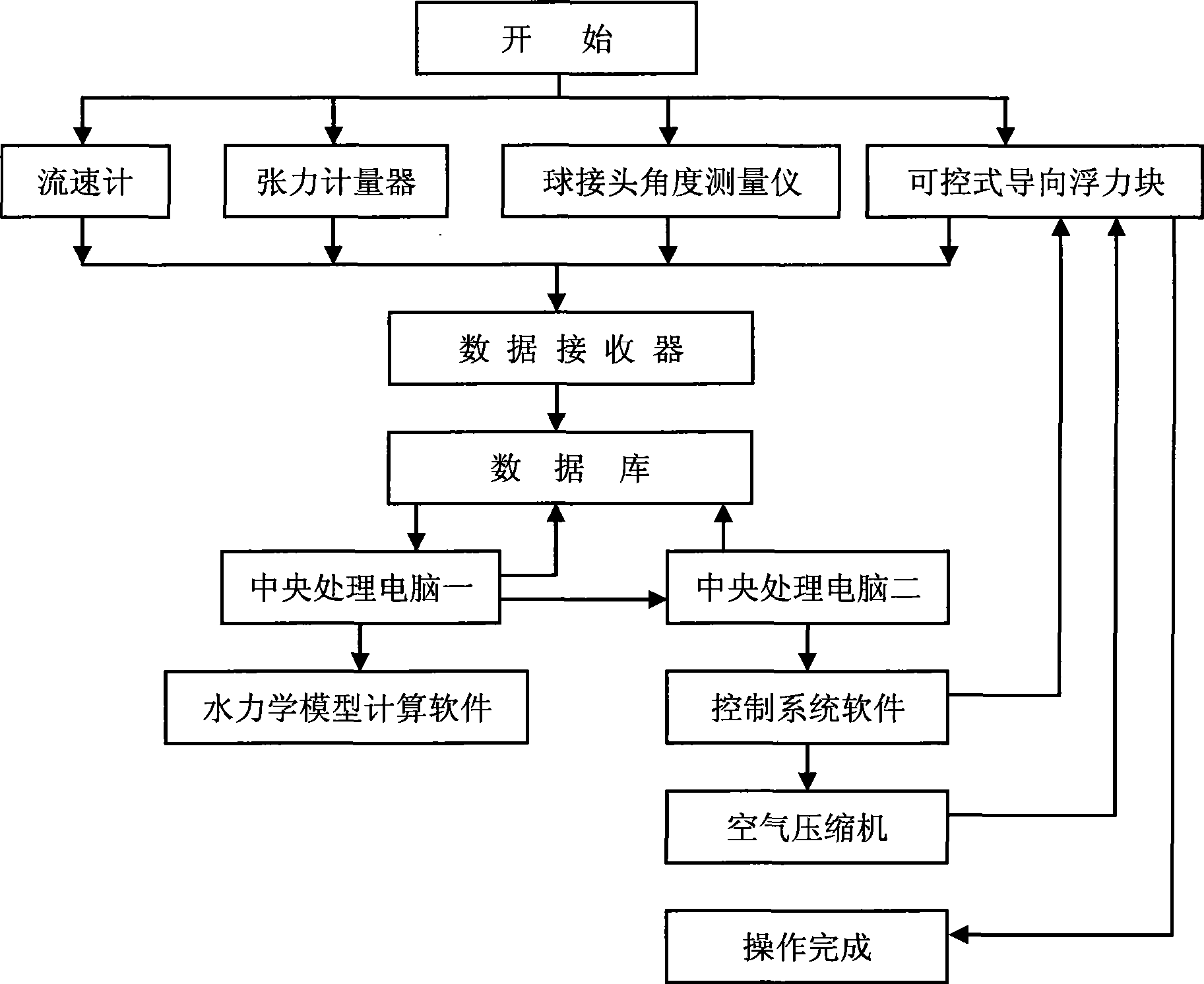
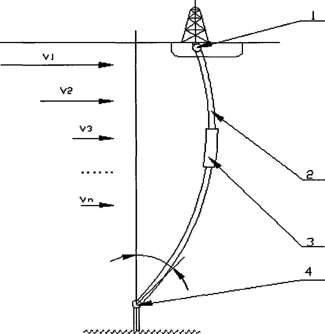
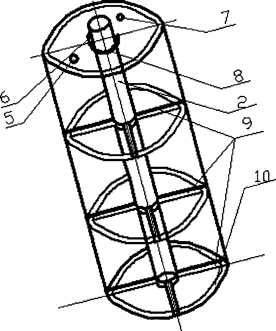
[0018] figure 1 , figure 2 Among them, the data receiver is connected with the current meter, the tensiometer, the controllable guide buoyancy block (3), and the ball joint angle measuring instrument, the data receiver is connected with the database, and the database is connected with the central processing computer. 1. Hydraulic model calculation software, Central processing computer 2. The control system software interacts with each other, and the control system software is connected with the air compressor and the controllable guide buoyancy block (3). System operation, current meter, tensiometer, controllable guide buoyancy block (3), ball joint angle measuring instrument to detect sea conditions and riser (2), upper ball joint (1), lower ball joint ...


PUM


Abstract

The invention relates to a set of buoyancy block closed loop control system applied to a deepwater marine riser, belonging to a specialized control system applied in the field of oceanic deepwater drilling engineering, aiming at providing a set of buoyancy block closed loop control system which can strengthen mechanical properties of the marine riser such as bending deflection resistance and fatigue failure resistance and improve safety and operation efficiency of deepwater drilling operation. In the control system of the invention, a data receiver is connected with a current meter, at least 3 tensiometers, a group of controllable guidance buoyancy blocks and two ball joint angular measuring meters; a database interacts with a central processing computer 1, a mechanical model calculation software, a central processing computer 2 and a control system software; the control system software is connected with an air compressor and the controllable guidance buoyancy blocks, the key component of the control system is a novel streamline controllable guidance buoyancy block. The key point of the technical proposal of the invention is: in accordance with actual calculating data of marine environment load, dynamic control of the operation conditions of marine riser system is realized by using the system software to control the buoyancy provided by the controllable guidance buoyancy blocks.

Description

technical field [0001] The invention relates to a closed-loop system for controlling the working state of a deep-water riser, in particular to a closed-loop control system for a buoyancy block of a deep-water riser, and belongs to a special control system for marine deep-water drilling engineering. Background technique [0002] With the development of my country's offshore oil industry and the continuous expansion of exploration and development fields, drilling operations are bound to enter the deep sea (water). Due to the change of drilling environmental conditions, the impact of deep water on drilling operations is the first to bear the brunt of the stability of the obviously lengthened riser. With the increase of water depth, the stress state of the riser string is more severe and complicated. There are many floating drilling ships or Due to the inability of the riser system to adapt and withstand the huge comprehensive external force, the drilling work of the platform is...

Claims


Application Information

Patent Timeline
IPC IPC(8): E21C50/00E21B44/00
Inventor 石晓兵黄兵刘运荣章浩炯王虎
Owner SOUTHWEST PETROLEUM UNIV
Learn More