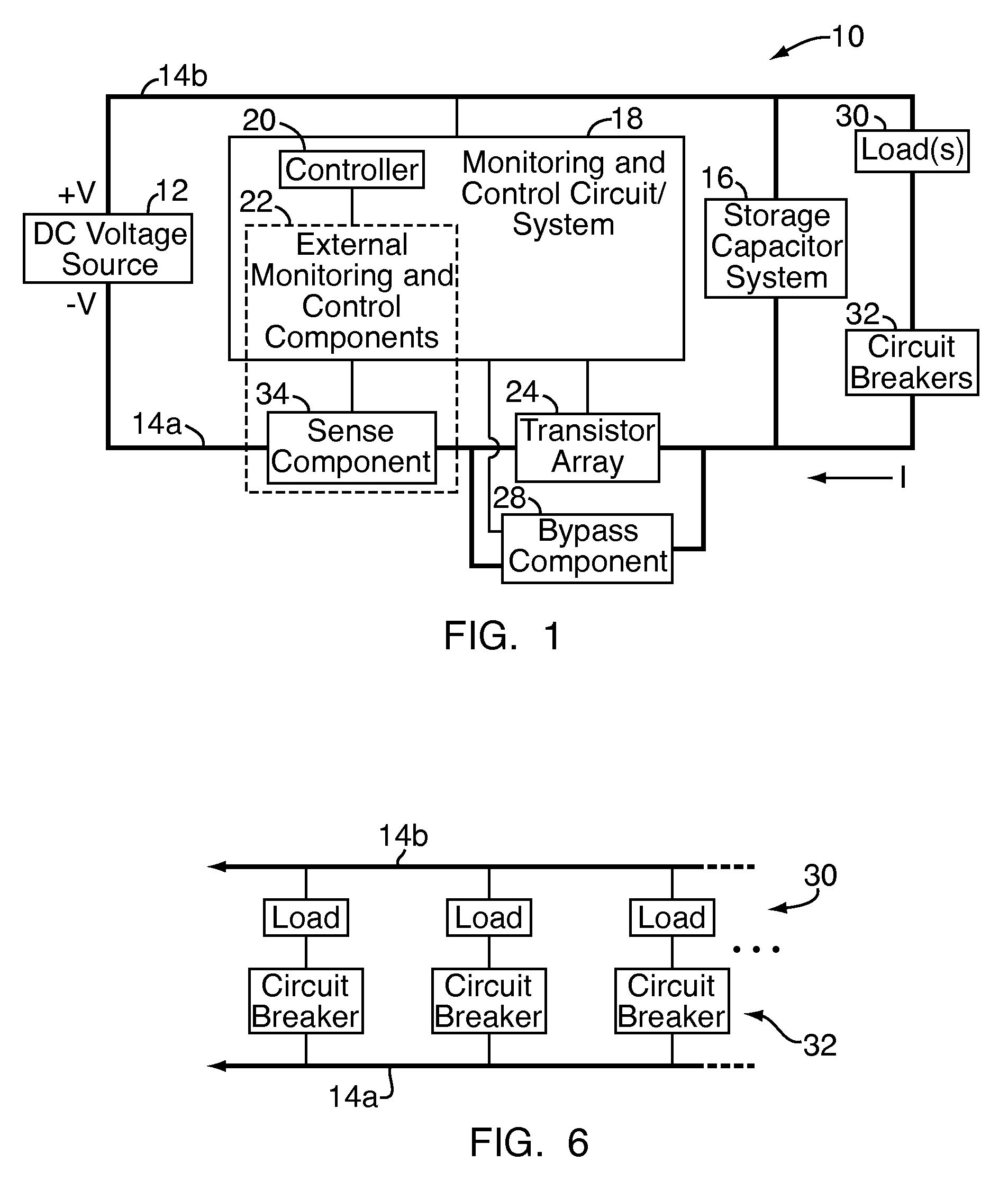
[0006]An embodiment of the present invention relates to a DC high power distribution
assembly for providing DC power to electronic devices, such as those for use in a telecommunication network or the like. The
assembly includes a
DC source (e.g., a
DC voltage applied across supply and return lines), a storage
capacitor system, and a
control circuit. A plurality of parallel-connected transistors is connected in series between the
DC source and the storage
capacitor system. A bypass component is connected in parallel to the transistors. (By “bypass component,” it is meant an electrical device or component controllable between an open / off state and a closed / on, low-resistance state.) The transistors and bypass component are connected to separate control outputs of the
control circuit. In operation, upon initial start-up of the distribution
assembly, the
control circuit activates the parallel-connected transistors for charging the storage
capacitor system, in a controlled manner for limiting
inrush current. Once the capacitors are charged (which typically occurs a short time before the transistors enter a fully on state), the control circuit activates the bypass component for
shunting the transistors. “Shunt” is used in its standard electrical sense, by which it is meant a low-resistance connection between two points in an electric circuit that forms an alternative path for a portion of the current. Thus, in this mode, which represents the
steady state operational mode of the distribution assembly for supplying DC power to a load, the primary
DC current is directed through the bypass component instead of through the transistors, reducing the amount of power consumed by the distribution assembly and eliminating the need for large
transistor heat sinks. (“Primary”
DC current refers to the
electrical current supplied to the load and / or storage capacitor system, which represents the bulk of the current handled by the distribution assembly.)
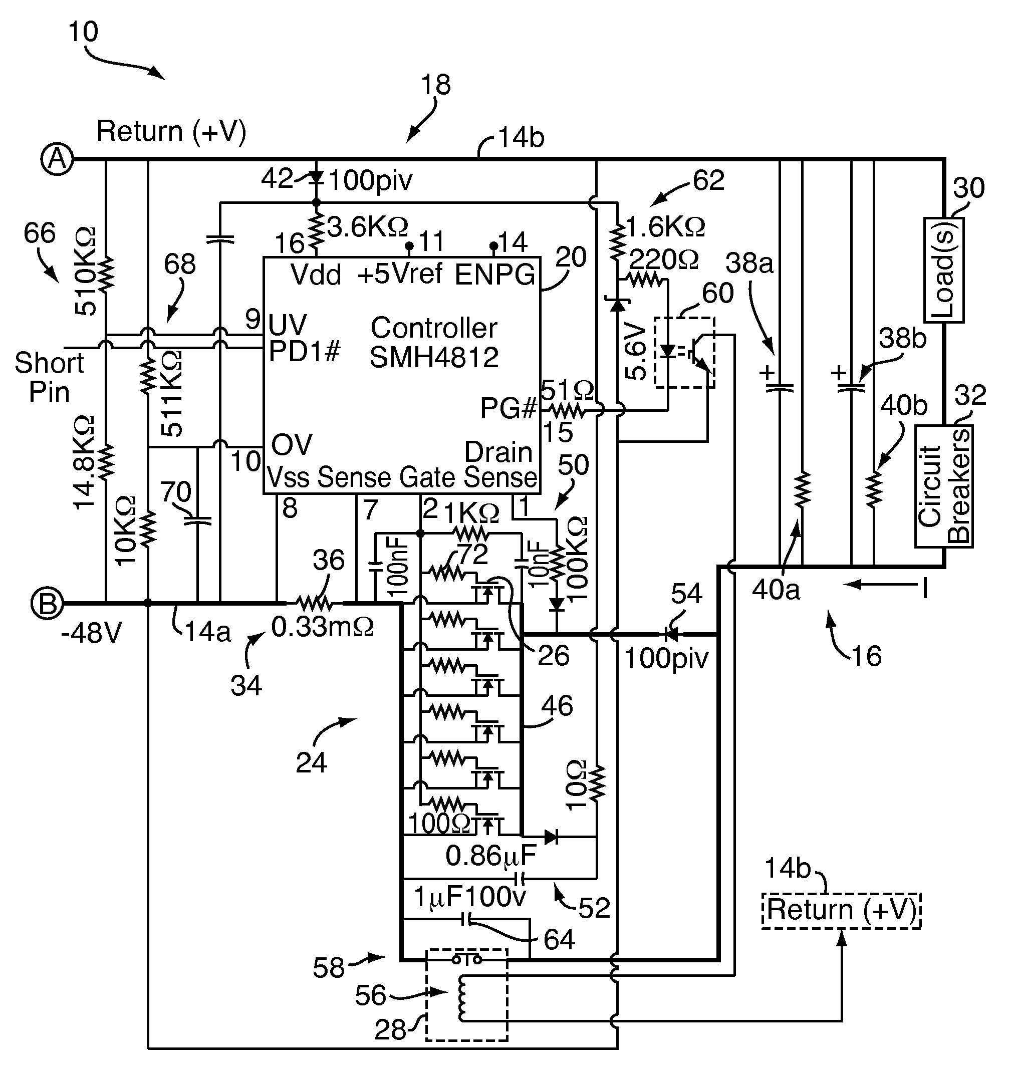
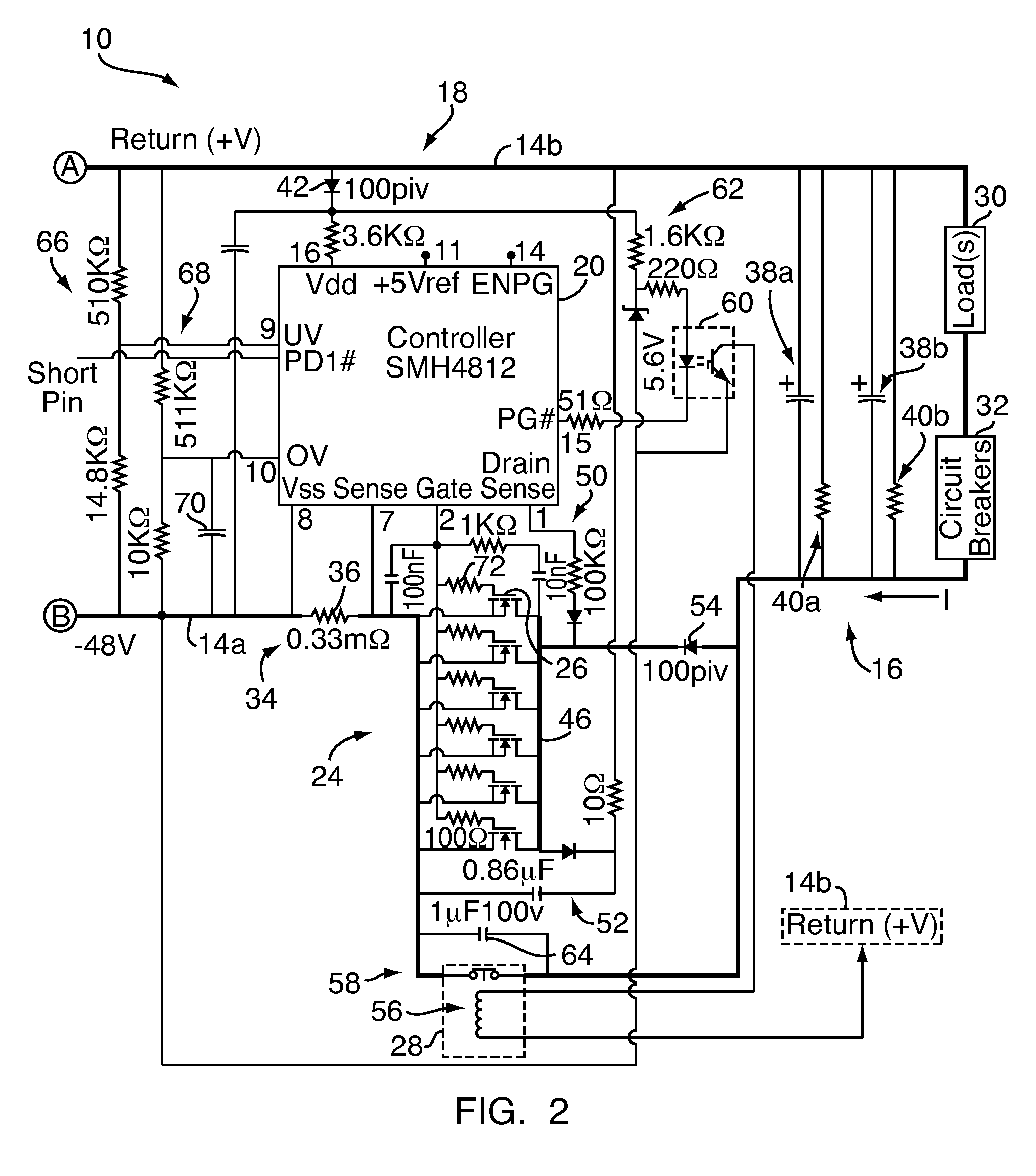
[0009]In another embodiment, the control circuit includes an IC (
integrated circuit) controller portion and one or more external sense components for use in monitoring the circuit conditions of interest. The controller includes various monitoring inputs and various control outputs, two of which are connected to the transistors and bypass component. The controller may be an existing, commercially available controller intended for use in other contexts, such as a hot-swap controller. (Hot-swap controllers prevent damage and operational faults in low-current applications where line cards or other circuit boards are inserted into an electrically live
backplane, typically by controlling a single FET or other
transistor to limit
inrush current when the
line card is first inserted. The FET then carries the primary current drawn by the
line card(s) during ongoing operation.)
[0010]In another embodiment, the parallel-connected transistors (typically there will be from 6 to 12 parallel-connected transistors) are arranged and configured in a highly symmetrical array, including possible provision of high-impedance gate resistors, to compensate for transistor
time delays and for current canceling in the transistors. This facilitates control of the multiple transistors by the controller, for placing the transistors in a linear operational state for a short time period for charging the storage capacitor system.
Inrush current is thereby limited even at
high current and power levels, e.g., 150 amperes at 8000 watts, without having to use a
resistor and large-sized
heat sink.
[0011]In another embodiment, an IC-based hot-swap controller is used in conjunction with (i) an array of parallel-connected transistors for controlling inrush current when charging the storage capacitor system, (ii) high capacity (where applicable) and other sense components for monitoring over-voltage, under-voltage, and over-current conditions, and (iii) a bypass component for bypassing the transistors during
steady state operation. In such a configuration, the power assembly is low cost, compact in size (e.g., no large heat sinks), allows for re-use, and provides both current inrush protection and advanced monitoring functions at very
high current and power levels.

