Determining Inserted Catheter End Location and Orientation

a catheter and end location technology, applied in the field of vascular access devices, can solve the problems of catheter not being located, picc procedure is not without complications, and uncertainty of the location and orientation of the picc line tip

Inactive Publication Date: 2008-07-24
US SEC THE AIR FORCE THE
View PDF20 Cites 15 Cited by
  • Summary
  • Abstract
  • Description
  • Claims
  • Application Information

AI Technical Summary

Benefits of technology

[0015]The invention described herein solves or substantially reduces in critical importance several problems associated with prior art catheterization devices by providing a device and a method for uniquely illuminating the catheter distal end in order to visualize the end-point location and orientation and to track the movement of the catheterization device within passageways in the body. Use of the present invention by tracking in real time with an imaging device sensitive to visible to near infrared light, including low level light detectors such as an image intensifier tube, night vision goggle, or charge coupled device (CCD), a metal-on-silicon (MOS) controlled imaging detector, and within certain limits, visible real time imaging with the unaided eye. The invention allows the insertion and tracking of substantially any catheterization type d...

Problems solved by technology

One of the difficulties frequently encountered in the placement of such catheters is said to involve the possibility of the catheter not being located in the intended position and in the intended configuration.
Because certain drug administration in some situations is location sensitive (because of tissue harm issues) either of these possibilities is undesirable.
The PICC procedure is not without complication however.
The most common difficulty with this procedure is in the uncertainty of the location and the orientation of the PICC line tip.
Unfortunately, however, normal bodily movements can alter the initial orientation and to some extent the placement a thin PICC line.
This is time consuming and expensive and carries the added risk to the patient of undesired exposure to ionizing radiation.
Therefore, the radiology procedure is often omitted because of reducing patient exposure to x-radiation, limited radiologist time, limited funding, and so-on.
This method can confirm accurate placement of a distal cannula tip terminating in the superior vena cava, but utility of this method is limited if the x-ray exposure time becomes so lengthy as to expose patient and attending practitioner to significant radiation levels.
The RF method may, however, result in elevated temperatures in the core of the body during the course of a catheter insertion by way of a diathermy-like process.
Utility of the method may be further limited by impedance mismatch between the RF driver and the coil or antenna that limit the strength of signals from the antenna.
Location is derived from analysis of...

Method used


Image

  • Determining Inserted Catheter End Location and Orientation
  • Determining Inserted Catheter End Location and Orientation
  • Determining Inserted Catheter End Location and Orientation

Examples


Embodiment Construction

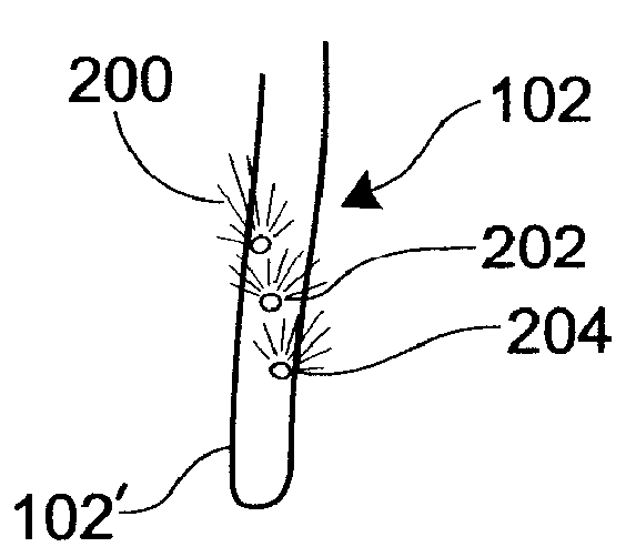
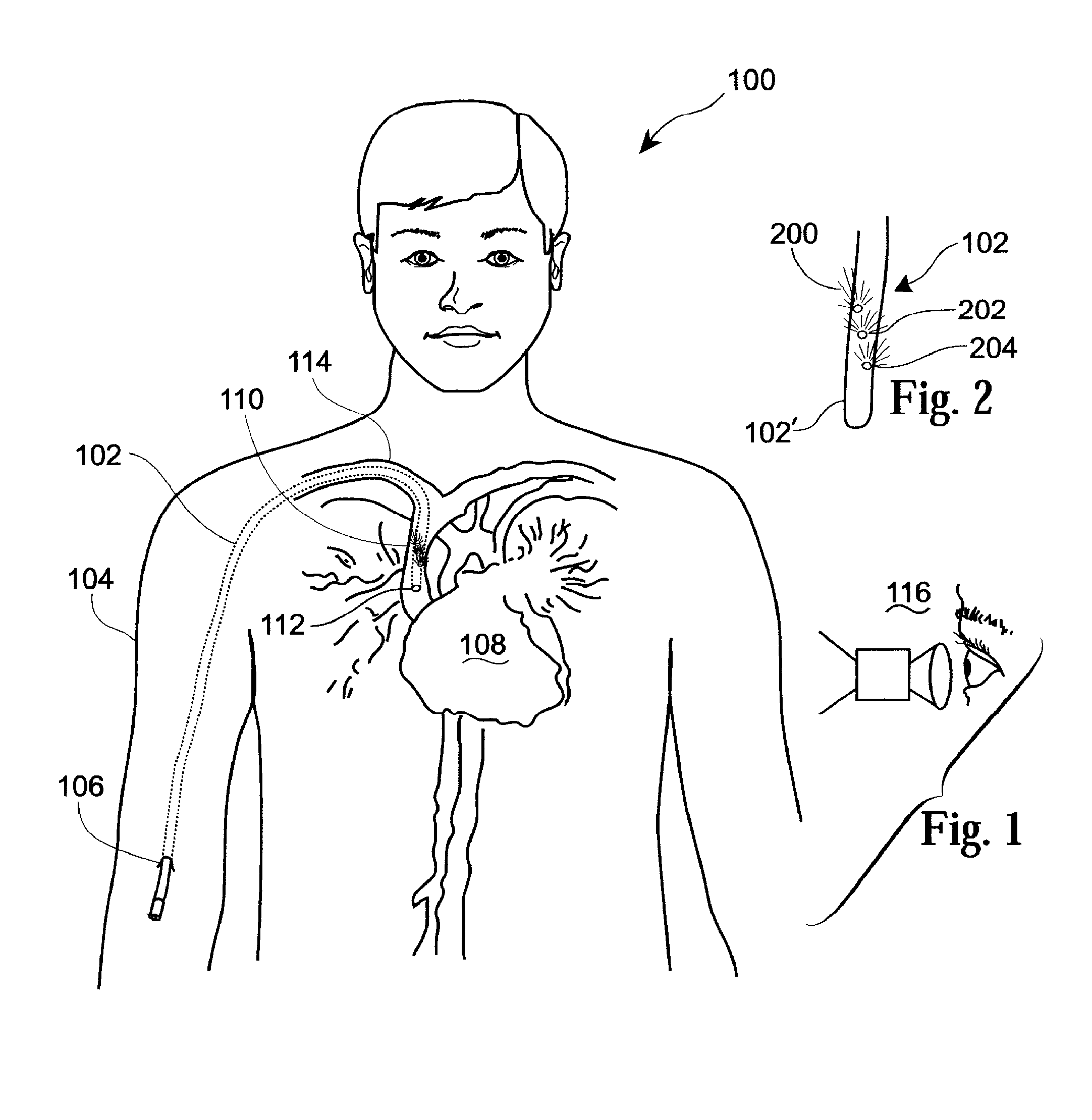
[0059]FIG. 1 in the drawings illustrates the placement and tracking within a human patient 100 of a catheterization or cannulation device 102 representative of the present invention. The device 102 is may be configured as substantially any catheterization or cannulation device, or in any other form for substantially any procedure requiring venal or arterial access such as for heart catheterization, angioplasty, or shunt placement or for urinary track catheterization, or other medical procedure requiring access to passageways of the body, such as in vascular, organ or subcutaneous access, the invention is herein described with reference to a representative embodiment of the invention in the form of a peripherally inserted central catheter (PICC) device 102.

[0060]In the representative device 102 shown in FIG. 1, and used as a PICC line, the device 102 is usually inserted into one of the large veins in the upper arm 104 near the elbow (e.g., into the basilic vein) by way of a skin open...


PUM


Abstract

Catheterization device and method of using are provided for uniquely illuminating the distal end of the device in order to visualize the end-point location and orientation and to track the movement of the catheterization device within passageways in the body. Use of the present invention by tracking in real time with an imaging device sensitive to visible to near infrared light. The invention allows the insertion and tracking of substantially any catheterization type device, for substantially any procedure requiring vascular access, such as in the placement of a PICC line, for heart catheterization or angioplasty, or for urinary track catheterization, or other bodily access procedure. The invention permits a technician to determine placement, orientation and movement of the device noninvasive equipment, without subjecting the patient to the hazards associated with ionizing radiation, radio frequency energy or significant thermal energy.

Description

STATEMENT OF GOVERNMENT INTEREST[0001]The invention described herein was made under a Cooperative Research and Development Agreement number 02-161-ML-01 with the Department of The Air Force. The Government of the United States has certain rights in the invention.FIELD OF THE INVENTION[0002]The invention described herein relates generally to medical devices and procedures for access to human or animal vasculature, and more particularly to device for vascular access that can be tracked with respect to location and orientation within the vasculature and a procedure for tracking the device.BACKGROUND OF THE INVENTION[0003]There are frequent medical situations in which it is desirable to insert a device into the vasculature, organ cavity, or other tubular body structure in a human or animal patient for diagnostic or for medical treatment procedures. Example procedures may include the placement of a catheterization or cannulation device into a part of the circulatory system (the vasculatu...

Claims


Application Information

Patent Timeline
IPC IPC(8): A61B5/05
CPCA61B5/06A61B5/0059
Inventor CRANE, ROBERT L.
Owner US SEC THE AIR FORCE THE
Why Eureka
Try Eureka