Plug-in battery charging booster for electric vehicle

a technology for electric vehicles and boosters, applied in the direction of battery/fuel cell control arrangements, electric devices, propulsion by batteries/cells, etc., can solve the problems of limited vehicle performance, unacceptably long charge period, limited electric current, etc., to optimize power usage, reduce the length of the charge period, and double the charging capacity

Inactive Publication Date: 2008-07-31
FORD GLOBAL TECH LLC
View PDF14 Cites 46 Cited by
  • Summary
  • Abstract
  • Description
  • Claims
  • Application Information

AI Technical Summary

Benefits of technology

[0011]The system employs a slow power ramp-up to prevent tripping a circuit breaker in power supply circuit. The system doubles the charging capacity and reduces the length of the charge period by about one-half.
[0012]The system and method pre-heat and / or pre-cool the vehicle passenger compartment at the end of battery charge cycle, and provide an adjustable delay time feature, which optimizes power usage by scheduling the battery charge period to off-peak periods when utility rates are lower than peak period rates.
[0013]This unique feature could help bring up the temperature of the fuel cell system, battery, and passenger compartment to help reduce unique limitations of cold fuel cell vehicle operation. While preheat the passenger compartment, the system uses a water-ethylene glycol (WEG) heater and other components to condition the vehicle optimally and efficiently. Protections are provided by the system to prevent and limit the amount of power used.

Problems solved by technology

However, in homes and most consumer locations the magnitude of electric current is limited by conventional circuit breakers to about 15 amps.
The length of the period to fully charge a traction battery is about &8 hours, which is unacceptably too long for most consumer usage.
Currently vehicles equipped with fuel cell systems present unique problems associated with low temperature operation including limited vehicle performance during a long fuel cell startup period, limited battery power availability, and a cold passenger compartment.
Unlike a vehicle equipped with an internal combustion engine, a vehicle equipped with a fuel cell system is subject to a lengthy warm-up period in cold temperature operation which limits vehicle drive-away performance.
Fuel cell systems provided limited ability to heat the passenger compartment heating using coolant heat because the coolant temperature remains low for a period following vehicle start-up.

Method used


Image

  • Plug-in battery charging booster for electric vehicle
  • Plug-in battery charging booster for electric vehicle
  • Plug-in battery charging booster for electric vehicle

Examples


Embodiment Construction

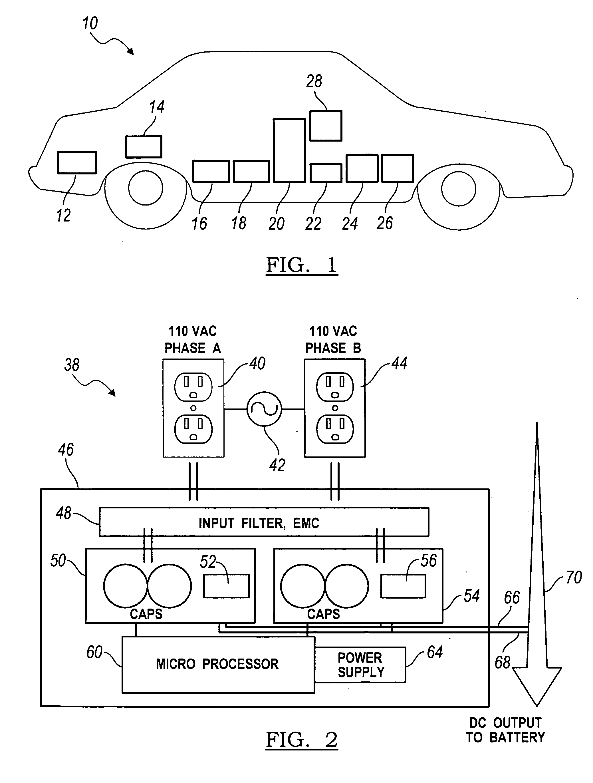
[0020]Referring to FIG. 1, a hybrid electric vehicle 10 is equipped with an electric machine 12, such as a starter-generator or traction motor; a high voltage (about 240-285V) electric storage battery 14 for supplying electric power to the traction motor 12; a low voltage (about 12V) service battery 16 for supplying power to vehicle lights, horn, and other vehicle accessories; a brake regeneration system 18 including a converter for recovering kinetic energy of the vehicle while being slowed by the wheel brakes and converting that energy to electric current stored in the battery 14; a second power source 20 such as an ICE or fuel cell for driving the motor and / or the vehicle wheels, and generating electric current for storage in battery 14; a microprocessor 22 for controlling the powertrain and other vehicle systems; an air conditioning compressor 24 driven by an electric motor, an electric heater 26 supplied with power from battery 14; and a WEG heater 28 supplied with power from b...


PUM


Abstract

A system for charging an electric storage battery in an electric vehicle includes a first converter electrically connectable to a first source of AC electric power, for converting AC from the first power source to a first DC output, a second converter electrically connectable to a second source of AC electric power that is out of phase relative to the first AC power source, for converting AC from the second power source to a second DC output, and a regulator electrically coupled to the first DC output, the second DC output and the battery, for producing and charging the battery with a third DC output having a higher voltage than the voltage of the first and the second DC outputs.

Description

BACKGROUND OF THE INVENTION[0001]1. Field of the Invention[0002]The preferred embodiment relates generally to a method and apparatus for charging a battery of a motor vehicle driven by electric power, and more particularly to a high voltage traction battery.[0003]2. Description of the Prior Art[0004]A hybrid electric vehicle is equipped with an electric machine, such as a starter-generator or traction motor, an electric storage battery for supplying electric power to the traction motor, a brake regeneration system including a converter for recovering kinetic energy of the vehicle as it is slowed by the wheel brakes and converting that energy to electric current stored in the storage battery, and a second power source such as an internal combustion engine (ICE) or fuel cell for driving the motor and / or the vehicle wheels and generating electric current that is stored in the battery.[0005]An external power source such as an electric utility power grid may be used to charge the battery...

Claims


Application Information

Patent Timeline
Patent Type & Authority Applications(United States)
IPC IPC(8): H02J7/04B60L1/00
CPCB60H1/00428Y02T10/70B60L11/1812B60L11/1816B60L11/1894Y02T90/14Y02T90/34Y02T90/127B60L1/003B60L1/06B60L3/0069B60L3/04B60L11/14B60L11/1803B60L11/1885B60L11/1887B60L2210/30B60L2210/40Y02T10/7077Y02T10/7241B60L1/02B60L50/16B60L50/51B60L53/14B60L53/22B60L58/31B60L58/34B60L58/40Y02T10/7072Y02T10/72Y02T10/88Y02T90/40H02J7/0072H02J7/022H02J7/04Y02T90/12
Inventor PATEL, BIJALGONZALES, PHILIP M.LEE, JOSEPHINE S.TO, VIET Q.STANEK, JOSEPH
Owner FORD GLOBAL TECH LLC
Why Eureka
Try Eureka