Volume Bragg grating laser mirror device

a laser mirror and volume bragg technology, applied in semiconductor lasers, instruments, optical elements, etc., can solve the problems of not being flexible, too simple, and prior art not meeting all users' requests on actual use, and achieves simple design, improved laser characteristics, and low cost.

Inactive Publication Date: 2008-08-07
NAT CENT UNIV
View PDF7 Cites 27 Cited by
  • Summary
  • Abstract
  • Description
  • Claims
  • Application Information

AI Technical Summary

Benefits of technology

[0004]The main purpose of the present invention is to obtain a wavelength of an output laser and a narrow laser output spe...

Problems solved by technology

However, they are too simple and are not flexible.
Hence, ...

Method used


Image

  • Volume Bragg grating laser mirror device
  • Volume Bragg grating laser mirror device
  • Volume Bragg grating laser mirror device

Examples


Embodiment Construction

[0026]The following descriptions of the preferred embodiments are provided to understand the features and the structures of the present invention.

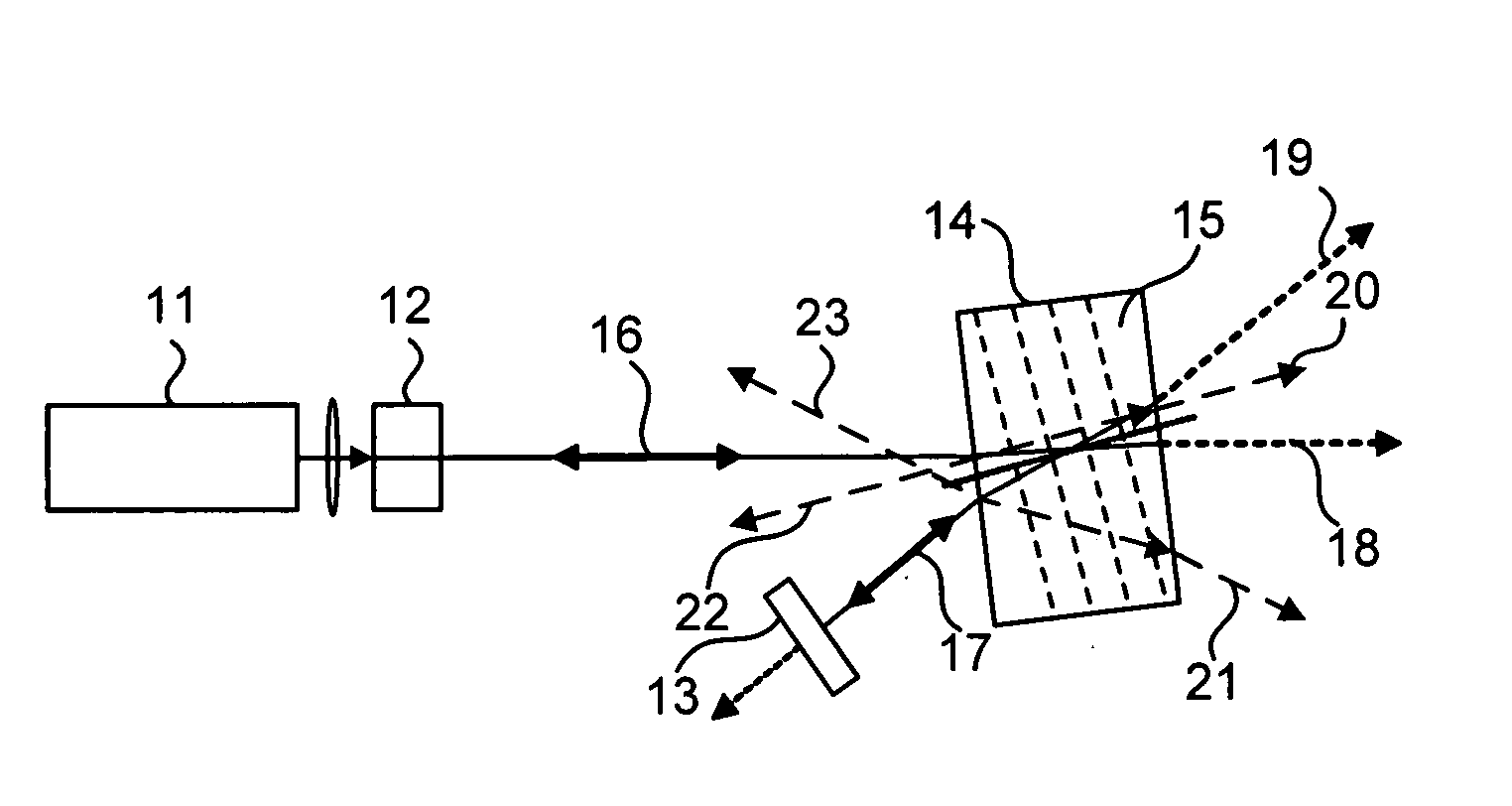
[0027]Please refer to FIG. 1, which is a view showing a first preferred embodiment according to the present invention. As shown in the figure, the present invention is a volume Bragg grating laser mirror device, comprising a 808 nanometer (nm) diode laser pump 11; a first reflector 12 doped with laser crystal; a second reflector 13; and a volume Bragg grating (VBG) 14 having a medium of photo-thermal refractive (PTR) glasses 14, where the first reflector 12 is further doped with a crystal of neodymium doped gadolinium vanadate (Nd:GdVO4) and is coated with a reflective film, or together with a transmissive film; the second reflector 13 is coated with a highly reflective film reflecting a 1064 nm (nanometer) wavelength and has a ˜99.7% reflection coefficient; the second reflector 13 is further doped with a crystal of neodymium doped yttrium...


PUM


Abstract

A volume Bragg grating (VBG) has a narrow wavelength. The wavelength is changed by changing an angle of the VBG or a temperature of the VBG. Thus, the present invention has a narrow wavelength, a bright laser, a simple system and an adjustable reflection for a wide application to laser systems.

Description

FIELD OF THE INVENTION[0001]The present invention relates to a volume Bragg grating; more particularly, relates to obtaining a wavelength of an output laser and a narrow laser output spectrum width.DESCRIPTION OF THE RELATED ARTS[0002]Using Bragg grating as a laser reflector is not a new idea. There are several patents as prior arts. Some fiber Bragg gratings are used to stabilize outputs of diode lasers in U.S. Pat. No. 6,125,222, U.S. Pat. No. 6,044,093 and U.S. Pat. No. 5,717,804. A fiber grating is used in fiber laser in U.S. Pat. No. 6,018,534. A vertical-cavity surface-emitting laser (VCSEL) obtained through epitaxy obtains films as Bragg gratings through various epitaxies for reflecting in U.S. Pat. No. 4,943,970. Some Bragg gratings are obtained on a surface through micro-lithography in U.S. Pat. No. 5,289,494 and U.S. Pat. No. 5,022,042. In the above prior arts, most are diode lasers and only few use other gain media. An example is U.S. Pat. No. 5,796,764, which use Nd:LiNb...

Claims


Application Information

Patent Timeline
IPC IPC(8): H01S5/125
CPCG02B5/1866H01S3/07H01S3/08036H01S3/0812H01S3/0815H01S3/083G02B19/0028H01S3/1055H01S3/1611H01S3/1643H01S3/1671G02B19/0052H01S3/09415
Inventor CHUNG, TE-YUAN
Owner NAT CENT UNIV
Why Eureka
Try Eureka