
Intake control device for internal combustion engine

a control device and internal combustion engine technology, applied in the direction of electric control, process and machine control, instruments, etc., can solve the problems of insufficient flow in the combustion chamber, and insufficient supply of higher fuel efficiency, so as to improve the combustion condition, reduce the effect of pumping loss and negative pressur

Inactive Publication Date: 2008-08-14
DENSO CORP
View PDF6 Cites 3 Cited by
  • Summary
  • Abstract
  • Description
  • Claims
  • Application Information

AI Technical Summary

Benefits of technology

[0009]The present invention has been made in view of these circumstances and has an object to provide an intake control device which meets the demand for improved fuel efficiency by increasing the flow velocity of intake air and thus increasing the intensity of intake air turbulent flow in the combustion chamber.
[0011]In this structure, since the opening-closing means which opens and closes one of the plural subpaths which has no air flow control valve is provided to control downstream-intake-pressure independently of upstream-intake-pressure by controlling opening and closing of the means while the air flow control valve is closed, the downstream-intake-pressure can be controlled so as to increase the pressure difference between upstream and downstream-intake-pressures. The flow velocity of intake air flowing through the subpath having no air flow control valve can be increased and the intensity of turbulent flow of intake air in the combustion chamber can be increased. The combustion condition can be further improved and higher fuel efficiency can be achieved.
[0013]In this structure, since the downstream-intake-pressure (intake pressure downstream of the opening-closing means) in the intake stroke of the internal combustion engine can be made higher than that in an internal combustion engine without an opening-closing means by the downstream-pressure-increase control, the cylinder internal pressure in the intake stroke can be increased (negative pressure is decreased) and pumping loss can be reduced. Consequently, even in a driving condition that a turbulent flow of intake air in the combustion chamber is less effective in improving the combustion condition (for example, during idling after warm-up), pumping loss can be reduced and fuel efficiency can be improved.

Problems solved by technology

However, the system has the following problem: the tumble port part is always open and the pressure difference between the intake pressure on the upstream of the tumble control valve and that on the downstream thereof cannot be increased sufficiently.
It is difficult to increase the flow velocity of intake air flowing through the tumble port part to increase the intensity of tumble flow and, as a consequence, demand for higher fuel efficiency cannot be met sufficiently.
The generation of a tumble flow in the combustion chamber is not so effective in improving fuel efficiency and fuel efficiency cannot be improved sufficiently.

Method used


Image

  • Intake control device for internal combustion engine
  • Intake control device for internal combustion engine
  • Intake control device for internal combustion engine

Examples


first embodiment

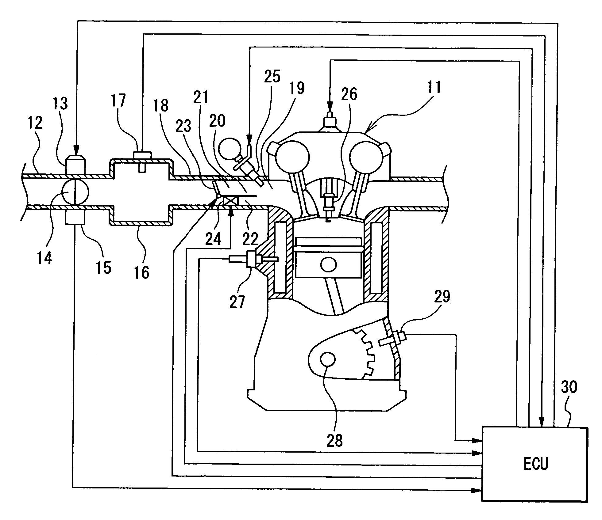
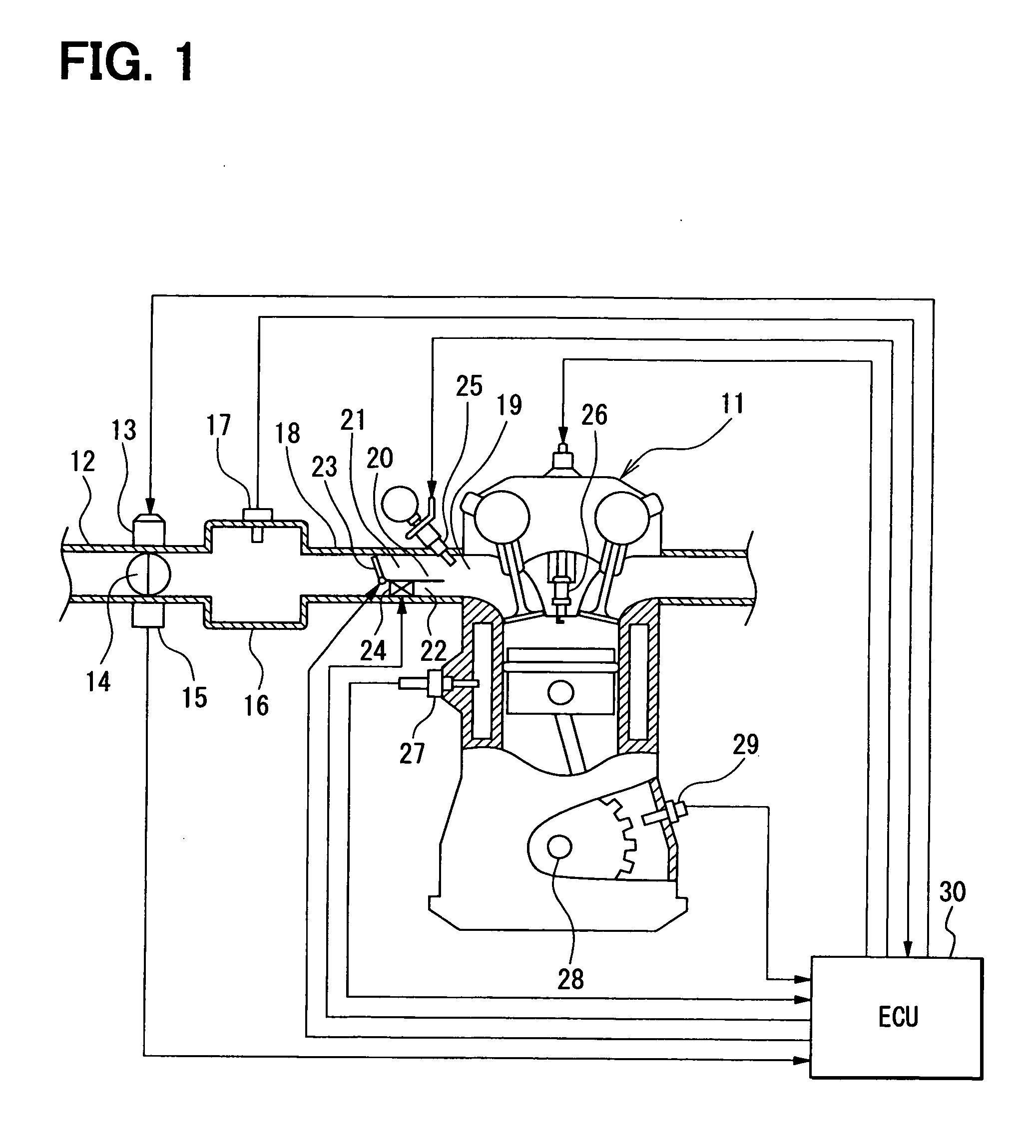
[0025]The general structure of an engine control system will be described referring to FIG. 1.

[0026]An internal combustion engine, for example, an in-line four-cylinder engine 11, has four cylinders (cylinders #1 to #4) and upstream of an intake pipe 12 of the engine 11, a throttle valve 14 the opening degree of which is controlled by a motor 13 and a throttle opening sensor 15 which detects the opening degree of the throttle valve 14 are provided.

[0027]A surge tank 16 is provided downstream of the throttle valve 14 and an intake pipe pressure sensor 17 for detecting intake pipe pressure is provided on the surge tank 16. An intake manifold 18 which introduces air into each cylinder of the engine 11 and the downstream portion of the intake manifold 18 of each cylinder is connected with the intake port 19 of each cylinder.

[0028]In the downstream portion of the intake manifold 18 or intake port 19 of each cylinder, there is provided a partition 20 which partitions the intake path into ...

second embodiment

[0057]In the first embodiment, as shown in the time chart of FIG. 7, downstream-pressure-increase control is carried out by controlling opening and closing of the intake pressure control valve 24 of each cylinder so as to make the downstream-intake-pressure higher than the in the system without an intake pressure control valve 24 (system in which the lower path 22 is always open) at least during the intake stroke of each cylinder of the engine 11 while the tumble control valve 23 of each cylinder is closed. In this downstream-pressure-increase control, the intake pressure control valve 24 of each cylinder is closed around the start of the intake stroke (for example, 30° CA after intake TDC) of the cylinder and opened during the explosion stroke after the end of the intake stroke of each cylinder (for example, 300° CA before intake TDC).

[0058]As indicated by solid line in FIG. 7, the intake pressure control valve 24 is closed around the start of the intake stroke to close the lower p...


PUM


Abstract

An intake control device of an internal combustion engine in which an intake path of each cylinder is partitioned into an upper and a lower path and a tumble control valve and an intake pressure control valve are provided to open / close the upper path and lower path respectively. In a given driving condition, the intake air flow velocity in the lower path is increased by closing the tumble control valve, thereby generating a tumble flow in the combustion chamber. In this process, the intake pressure control valve is opened around start of an intake stroke and closed around its end to make intake pressure downstream of the intake pressure control valve higher than upstream of it to increase the difference between upstream and downstream intake pressures in the intake stroke. This increases the intake air flow velocity in the lower path and intensifies the tumble flow in the combustion chamber.

Description

CROSS-REFERENCE TO RELATED APPLICATION[0001]This application is based on Japanese Patent Applications NO. 2007-31351 filed on Feb. 9, 2007, and No. 2007-32944 filed on Feb. 14, 2007, the disclosure of which is incorporated herein by reference.FIELD OF THE INVENTION[0002]The present invention relates to an intake control device for an internal combustion engine which generates a turbulent flow of intake air by means of an air flow control valve provided in an intake path of the engine.BACKGROUND OF THE INVENTION[0003]Japanese Patent No. 3671755 discloses an intake control device in which the intake port of an internal combustion engine is partitioned into an upper port part and a lower port part by a partition wall. One of these port parts is closed by a tumble control valve to let intake air flow only through the other port part. The flow velocity of intake air is thus increased and a tumble flow (vertical turbulent flow of intake air) is generated in the combustion chamber so as to...

Claims


Application Information

Patent Timeline
Patent Type & Authority Applications(United States)
IPC IPC(8): F02B17/00
CPCF02B17/005F02B23/10Y02T10/146F02B2023/106Y02T10/125F02B31/04Y02T10/12
Inventor MIYANAGA, HIROAKINAKASHIMA, KAZUSHINAKABAYASHI, KATSUHIKO
Owner DENSO CORP
Learn More