Control Device of a Stopper-Rod

Inactive Publication Date: 2008-08-14
DANIELI & C OFF MEC SPA
View PDF4 Cites 2 Cited by
  • Summary
  • Abstract
  • Description
  • Claims
  • Application Information

AI Technical Summary

Benefits of technology

[0008]A primary object of the present invention is to produce a control device of a stopper-rod, or

Problems solved by technology

Notwithstanding the type of motor, the response time is limited by the mechanical play of the system, which prevents precise control of the operating position.
The disadvantages of these devices are: low response times; complexity of the parts; higher number of mechanical components that produce play, with consequent imprecise control of regulation and the need to perform maintenance on the system.
Given the presence of play, the position of the stopper-rod must also be measured by means of a linear transducer directly on the stopper arm, said sensor typically being delicate and subject to malfunctioning.
On the other hand, hydraulic or hydrodynamic devic

Method used


Image

  • Control Device of a Stopper-Rod
  • Control Device of a Stopper-Rod
  • Control Device of a Stopper-Rod

Examples


Embodiment Construction

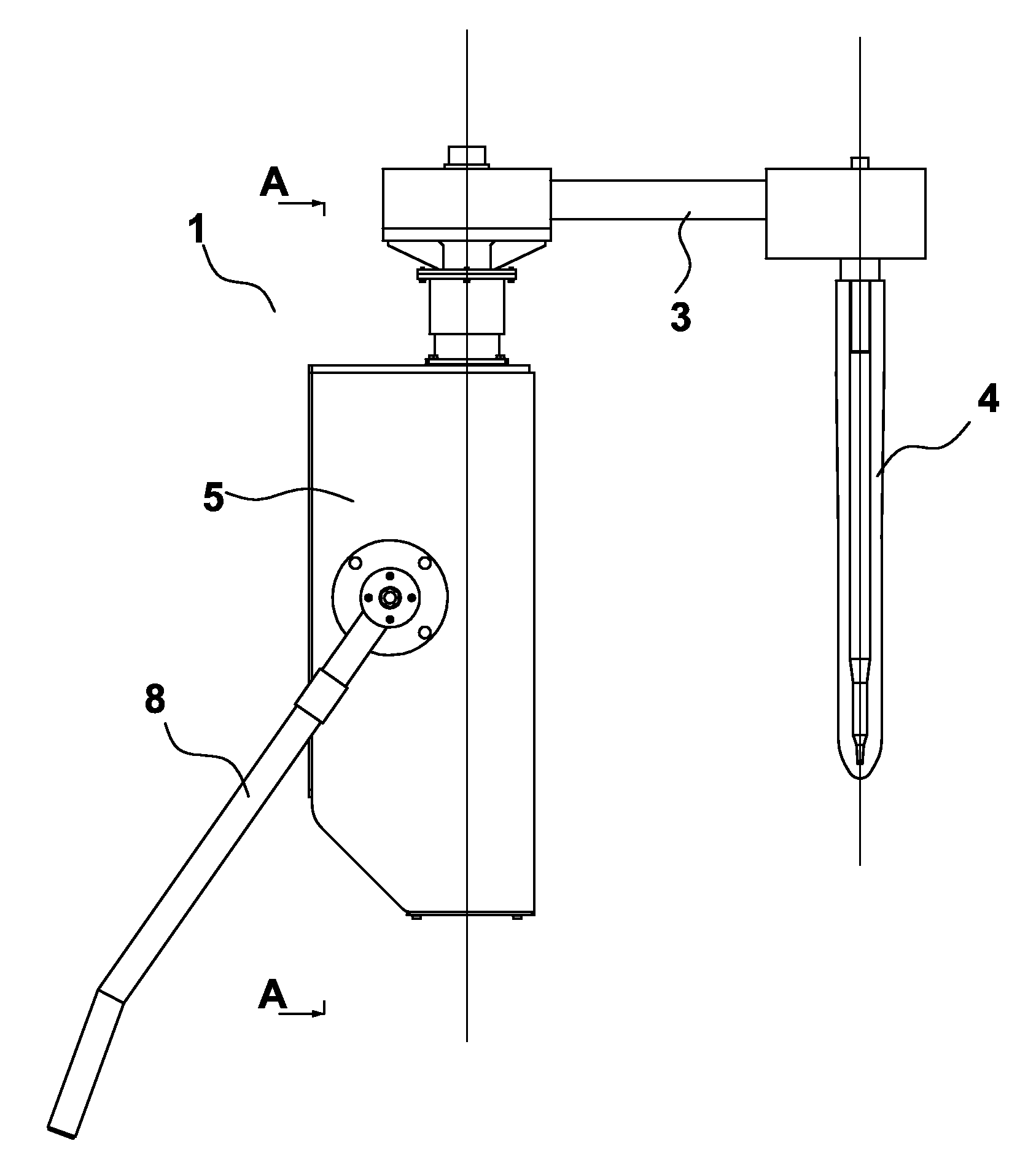
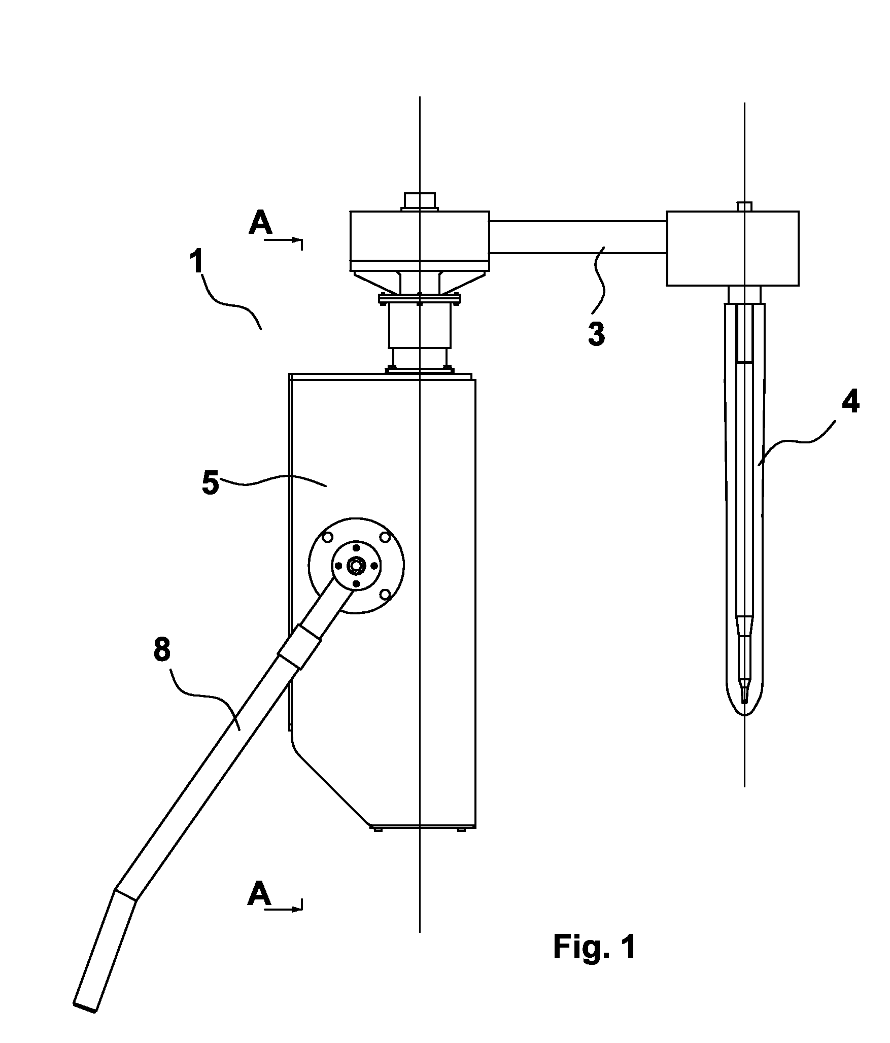
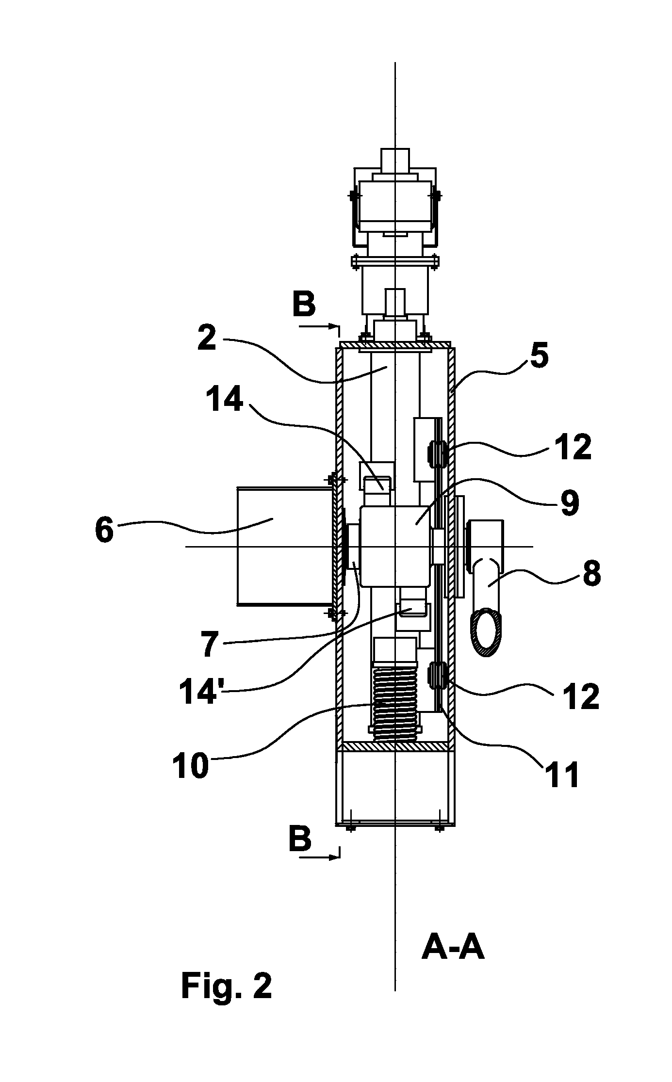
[0017]With reference to the figures, a control device for a stopper, indicated as a whole with the reference numeral 1, is represented. This device comprises:[0018]motor means 6,[0019]a drive shaft 7,[0020]motion conversion means 14, 14′;[0021]a lifting and lowering rod or stem 2;[0022]a connection element or arm 3.

[0023]The motor means, for example a planetary gearmotor 6, impart motion to the lifting and lowering rod or stem 2, housed in a retaining frame 5. Said gearmotor 6, or motor, has reduced dimensions, especially the axial dimensions; it has low inertia; reduced play; high rigidity and high power.

[0024]The direct drive gearmotor 6 is keyed onto one end of the drive shaft 7, essentially horizontal and passing through the retaining frame 5, while at the other end thereof an extractable lever 8 is fitted for manual control of the rod 2. Both the motor and the lever for manual control are outside the retaining frame.

[0025]Advantageously, the suspension bearing of the shaft does...


PUM

PropertyMeasurementUnit
Flexibilityaaaaaaaaaa
Elasticityaaaaaaaaaa

Abstract

Control device for a stopper-rod to regulate the outflow of liquid metal through a calibrated hole of a pouring receptacle comprising motor means, suitable to operate lifting and lowering means (2) of the stopper (4) by means of first driving means (7) and second driving means (14, 14″), the latter being suitable to convert a rotating motion into a translational motion, wherein the second driving means are flexible longitudinal elements and are fixed at a first end thereof to lifting and lowering means and a second end thereof to an anchor element (9), integral with the first means.

Description

FIELD OF THE INVENTION[0001]The present invention relates to a control device of a stopper, in particular of a stopper-rod used to regulate the outflow of liquid steel through a ladle or a tundish.PRIOR ART[0002]The stopper-rod, or simply stopper, is the device which interacts with a calibrated hole or nozzle to regulate the outflow of liquid steel through a ladle or a tundish. Continuous regulation of the stopper takes place as a function of the level of steel in the ingot mould which is continuously monitored by a radioactive sensor that sends a signal to a programmable logic controller which, in turn, controls the motor of the device to control or move the stopper. The control device must control the stopper so as to continuously guarantee a stable meniscus in the pouring receptacle, and therefore it must allow a high operating speed of said stopper, especially for high pouring speeds. Two types of control device are known: one electromechanical and one hydraulic. Having defined ...

Claims


Application Information

Patent Timeline
IPC IPC(8): B22D41/20
CPCB22D41/20
Inventor POLONI, ALFREDODE LUCA, ANDREADAVID, CLAUDIO
Owner DANIELI & C OFF MEC SPA
Why Eureka
Try Eureka