
Vibration Isolation

Active Publication Date: 2008-08-14
BAE SYSTEMS PLC
View PDF9 Cites 22 Cited by
  • Summary
  • Abstract
  • Description
  • Claims
  • Application Information

AI Technical Summary

Benefits of technology

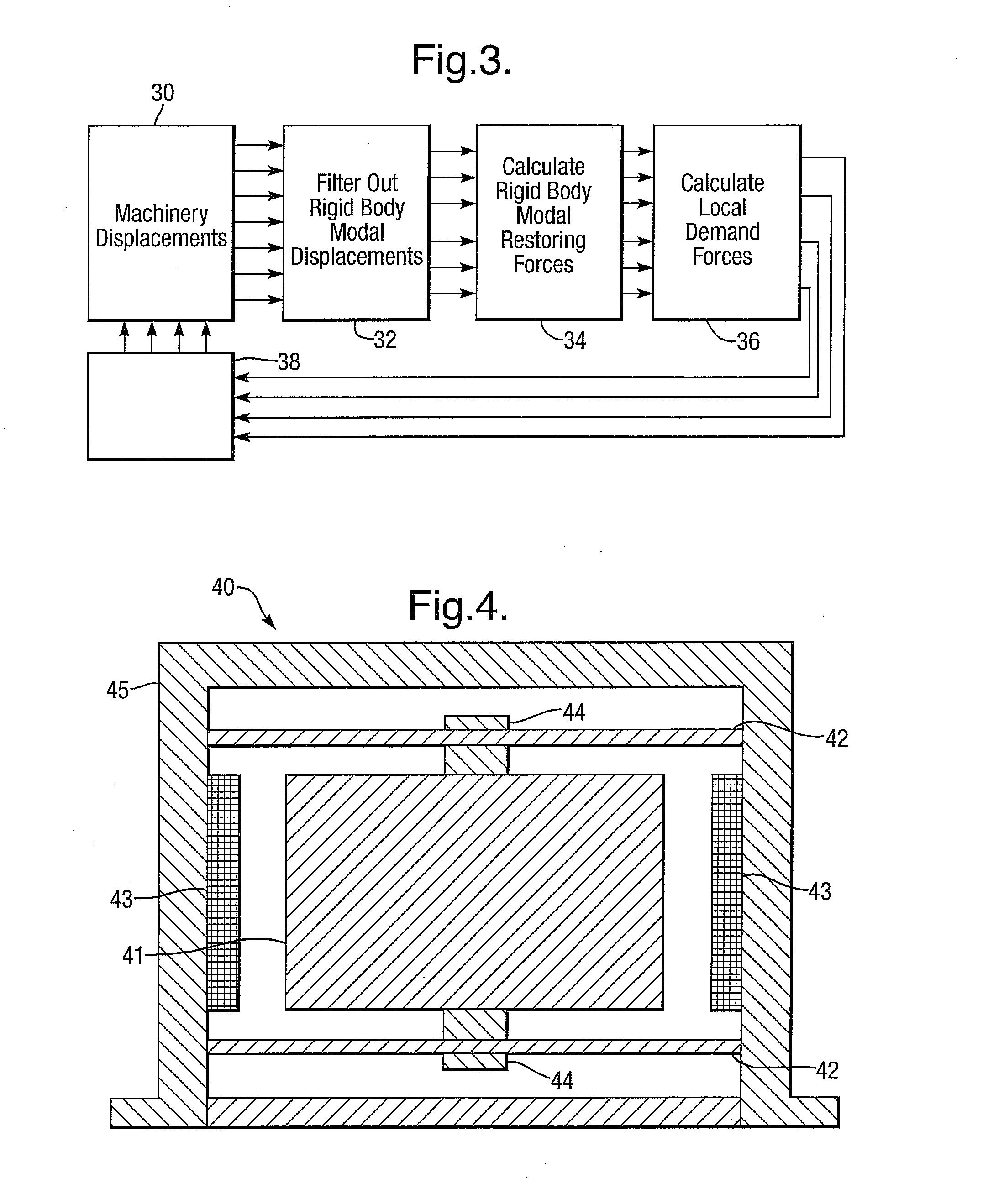
[0010]and controlling said active isolation means of each said mount such that below said resonant frequency a performance parameter, primarily stiffness, of each mount is essentially that of the passive resilient means, and controlling said active isolation means of each said mount such that, above said mount resonant frequency at least over a desired frequency band, essentially a zero stiffness of the mount is maintained to excited structural resonances, and such that rigid body modes of movement of said support are compensated, preferably minimised
[0027]Thus the present invention provides a much simpler approach than the prior art to the problem of vibration isolation that may give an even better performance with greatly reduced complexity and hence cost. It makes use of a relatively small number of controlled mounts that ignore local displacements while controlling the response of the machinery's rigid body modes only. This ensures that excited resonances in the mounted structure and the machinery do not generate forces on the hull.

Problems solved by technology

Working machinery is a major source of vibration in marine vessels and considerable effort is devoted to developing isolation systems that reduce transmission to the hull.
A particular problem associated with machinery isolation in marine environments is structural resonance.
Such resonance leads to very high forces transmitted across machinery mounts, and this poses a very significant vibration problem.
Moving machinery generates a complex spectrum of out-of-balance forces and in marine vessels considerable effort is devoted to developing resilient mounting systems that reduce the transmission of these forces across the machinery mounts to the hull.
Above this frequency the force transmissibility is generally decreasing with increasing frequency and this results in forces generated by machinery vibrations being attenuated before arriving at the hull.
However, the force attenuation in this regime may be dominated by structural resonances.
Out-of-balance forces, generated by the moving machinery, result in both linear and angular displacements of the supported structure.
A difficulty with this simple approach is that the large non-linearity of the electromagnet makes a simple feedback control unsatisfactory.

Method used


Image

  • Vibration Isolation
  • Vibration Isolation
  • Vibration Isolation

Examples


Embodiment Construction

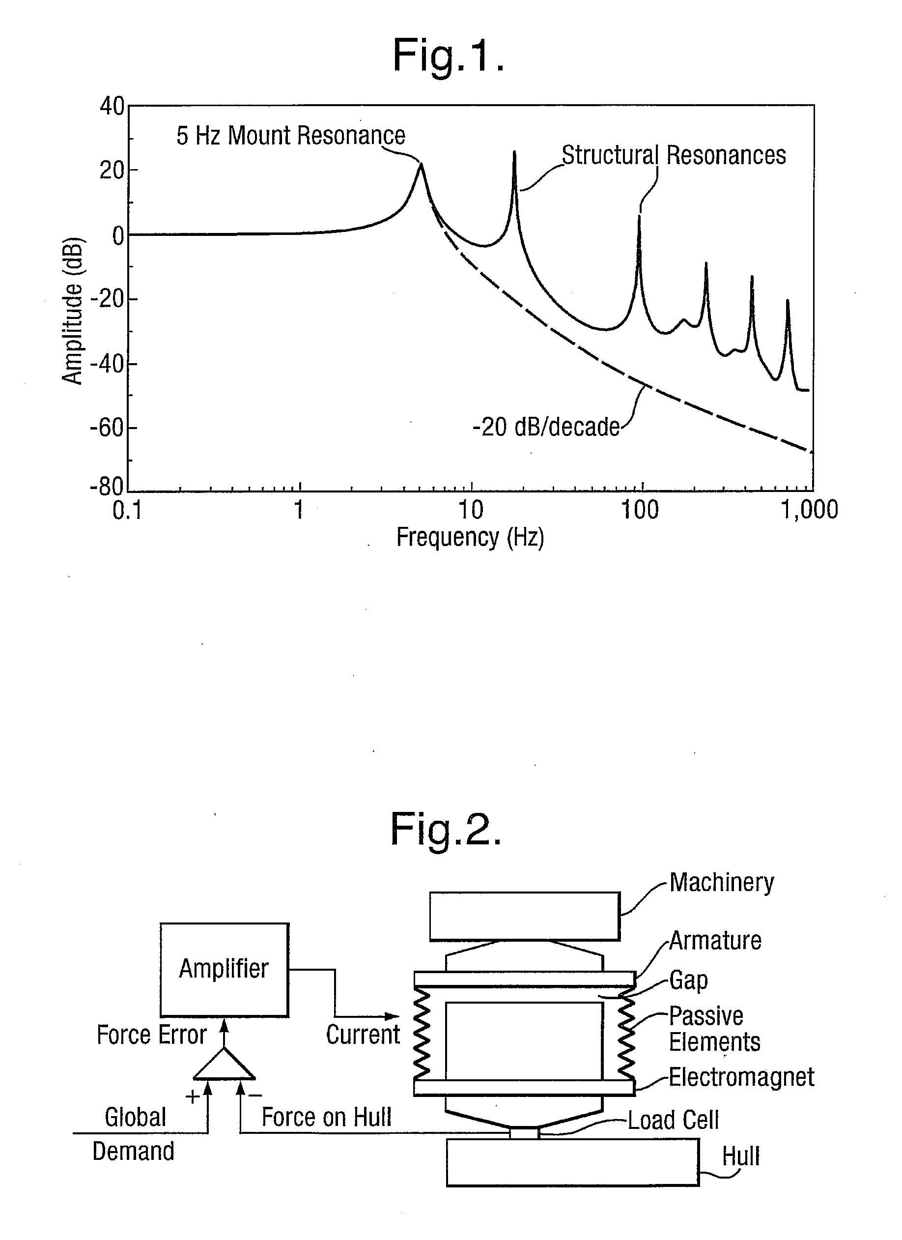
[0052]The motions of a flexible structure can be described as a superposition of normal modes. These consist of the six zero frequency rigid body modes: three translational modes, surge, sway and heave; three rotational modes, roll, pitch and yaw, and the finite frequency structural resonant modes. If the composite mounts of a mounting system for rotating machinery are made to act on the six rigid body modes only, while simultaneously ignoring displacements due to excited resonances, the force transmissibility, for the heave mode, would be as shown by the monotonic descending line curve in FIG. 1. It will be seen that near and below the 5 Hz mount resonant frequency the force transmissibility is unchanged but above this frequency there is a major improvement in vibration isolation. All the structural resonant peaks, and hence the associated acoustic signature, have disappeared and the force transmissibility is systematically falling at the rate of dB / decade.

[0053]In order to achieve...


PUM

PropertyMeasurementUnit
Forceaaaaaaaaaa
Angleaaaaaaaaaa
Frequencyaaaaaaaaaa

Abstract

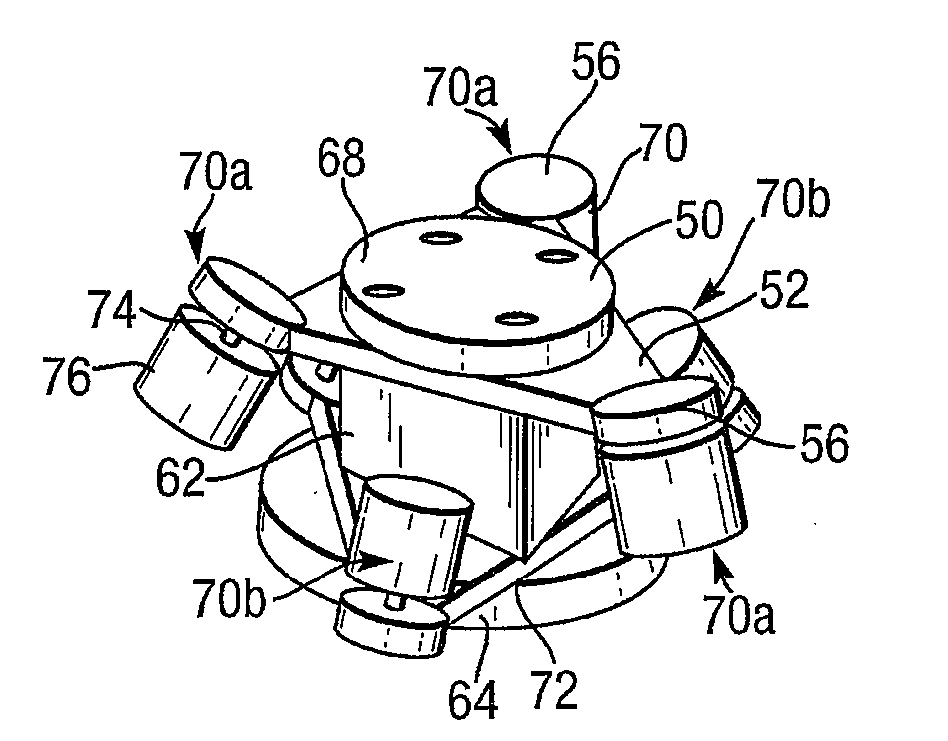
A support for machinery, and for isolating vibration from the machinery, comprises a plurality of mounts, each mount comprising an elastomeric block for completely supporting the static load of the machinery, and active isolation means comprising inertial shakers arranged to maintain essentially a zero stiffness of the mount to excited structural resonances over a desired frequency band above said mount resonant frequency, and to modify the transmission of out of balance forces to the hull. A control system coupled to the inertial shakers includes a means for applying damping force signals, such as to dampen structural resonances, to inhibit the onset of resonant vibration.

Description

TECHNICAL FIELD[0001]The present invention relates to method and apparatus for isolating vibrations of machinery from its surroundings, particularly though not exclusively rotating machinery for marine vessels.BACKGROUND ART[0002]Working machinery is a major source of vibration in marine vessels and considerable effort is devoted to developing isolation systems that reduce transmission to the hull. A particular problem associated with machinery isolation in marine environments is structural resonance. This occurs principally in the machinery support structure. Such resonance leads to very high forces transmitted across machinery mounts, and this poses a very significant vibration problem. Moving machinery generates a complex spectrum of out-of-balance forces and in marine vessels considerable effort is devoted to developing resilient mounting systems that reduce the transmission of these forces across the machinery mounts to the hull.[0003]A common approach to vibration isolation is...

Claims


Application Information

Patent Timeline
IPC IPC(8): F16F15/03F16F7/10
CPCF16F7/1011F16F15/03Y10T29/49901F16F15/22F16F2228/06F16F7/10
Inventor JOHNSON, FREDERICK A.DALEY, STEPHEN
Owner BAE SYSTEMS PLC
Learn More