Polymeric Strain Sensor

a technology of polymeric strain and sensor, which is applied in the direction of organic conductors, non-conductive materials with dispersed conductive materials, conductive materials, etc., can solve the problems of micromechanical hysteretic dislodgement, and achieve the effect of convenient manufacture and us

Inactive Publication Date: 2008-08-14
ROYAL MELBOURNE INST OF TECH
View PDF7 Cites 19 Cited by
  • Summary
  • Abstract
  • Description
  • Claims
  • Application Information

AI Technical Summary

Benefits of technology

[0017]This SSE can easily be manufactured and used in any shape or size including, thin or thi

Problems solved by technology

The proposed composition is well below the percolation threshold compared to prior art composite sensors that rely on physical con

Method used


Image

  • Polymeric Strain Sensor
  • Polymeric Strain Sensor
  • Polymeric Strain Sensor

Examples


Embodiment Construction

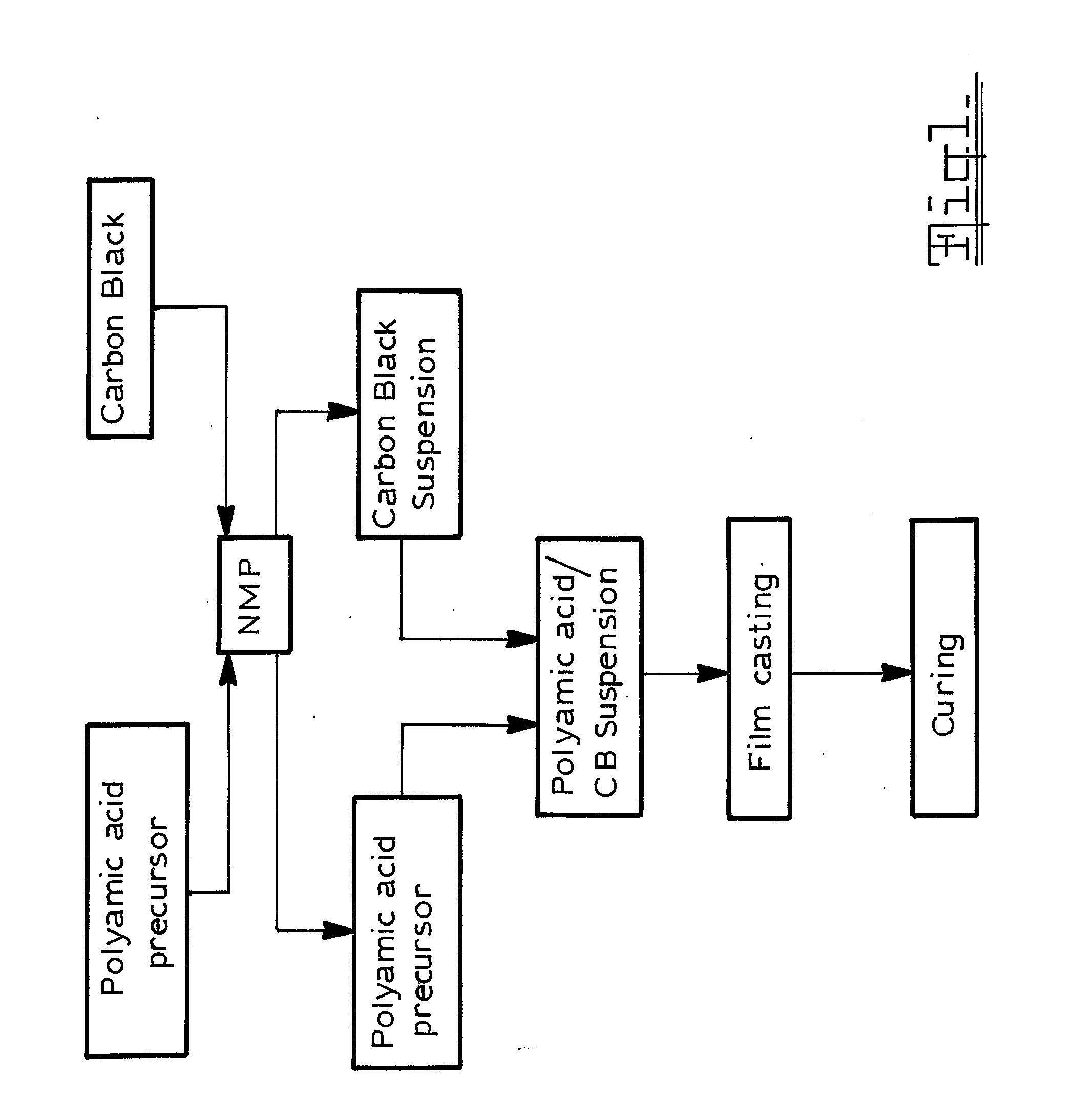
[0020]FIG. 1 illustrates the fabrication steps used in one embodiment of this invention;

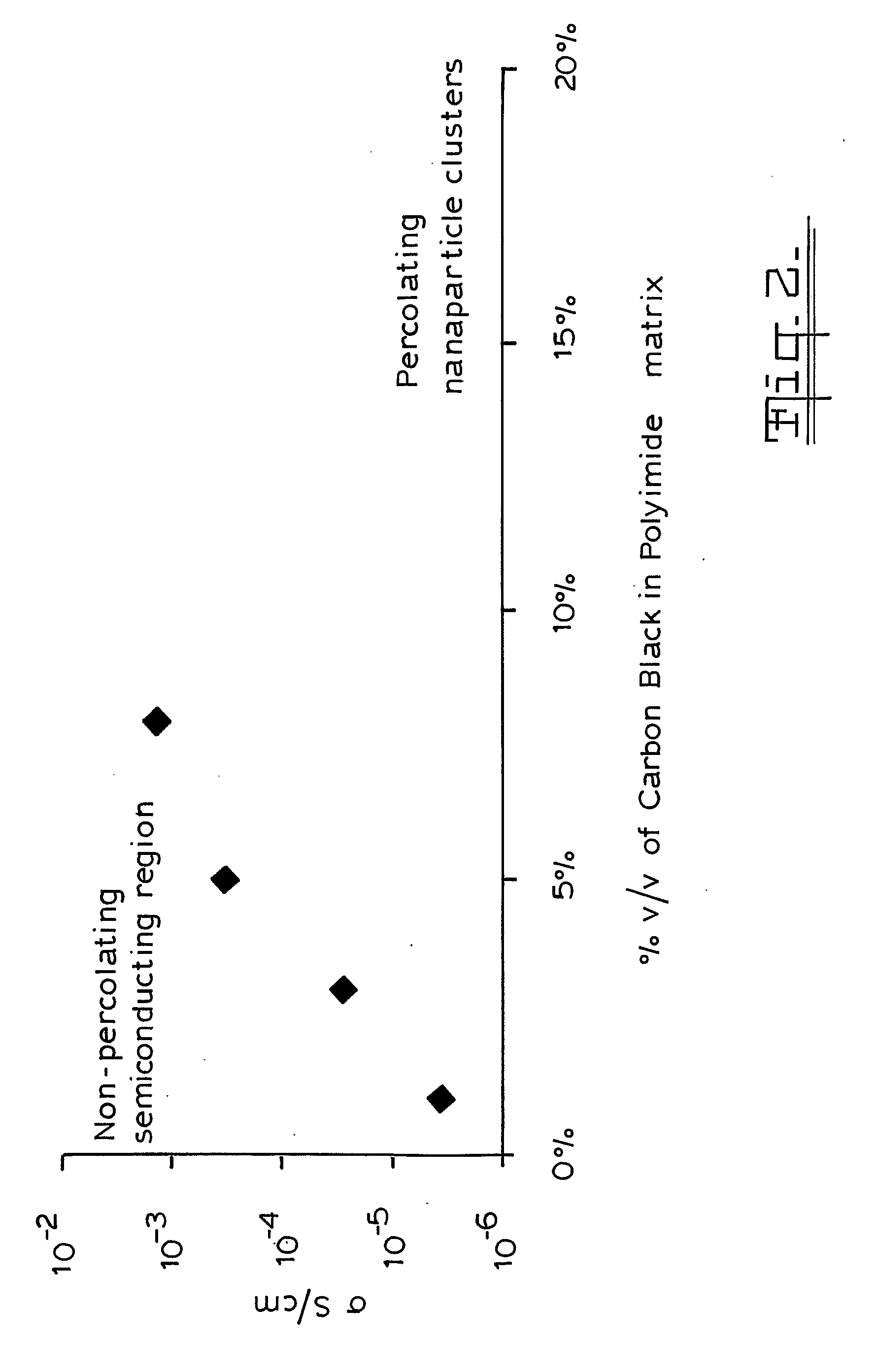
[0021]FIG. 2 illustrates the variation of electrical conductivity with carbon content at 20° C.;

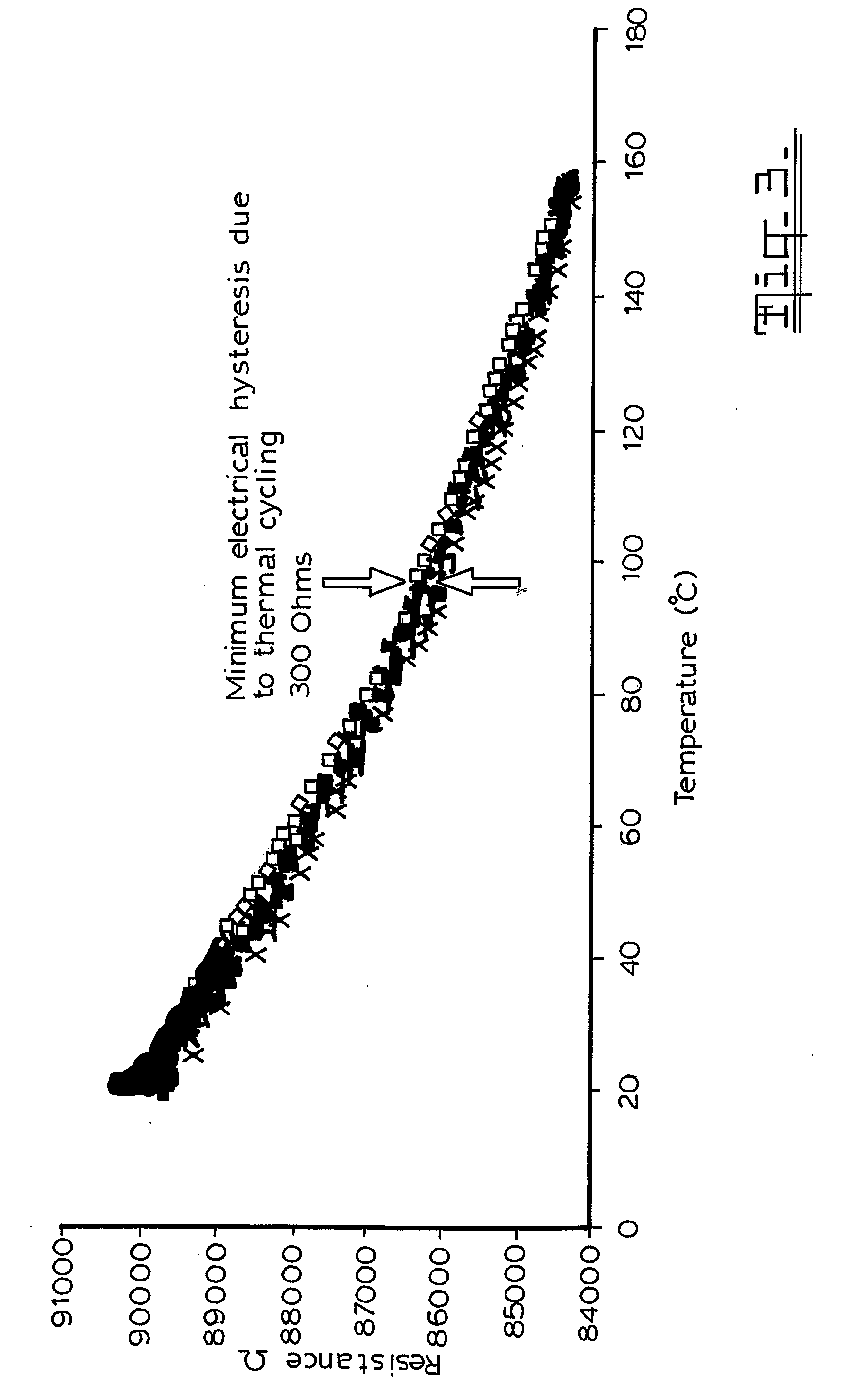
[0022]FIG. 3 illustrates Temperature Dependent electrical resistance variation between a free standing and a supported film;

[0023]FIG. 4 illustrates the electrical hysteresis due to thermal cycling;

[0024]FIG. 5 illustrates typical micromechanical behaviour of the sensor of this invention compared to the unfilled polymer;

[0025]FIG. 6 illustrates typical electromechanical behaviour of the sensor of this invention;

[0026]FIG. 7 illustrates the strain resistance change and the gauge factor of the sensors of this invention;

[0027]FIG. 8 is a schematic representation of the carbon fibre composite rowing Oar showing the locations of the SSEs that were placed along the axis of the Oar;

[0028]FIG. 9 is a graph of resistance ratio plotted against time obtained for the strain sensor elements during cyclic deformatio...


PUM


Abstract

A strain sensor consisting of a non conducting polymer incorporating conductive nanoparticles below the percolation threshold and preferably less than 10% v/v of the polymer. The polymer is a polyimide and the conducting nanoparticle is carbon black having an average particle size of 30-40 nm and an aggregate size of 100-200 nm. The sensor can sense strain in extension, compression and torsion.

Description

BACKGROUND TO THE INVENTION[0001]Polymeric strain gauges have been proposed.[0002]U.S. Pat. No. 5,989,700 discloses the preparation of pressure sensitive ink that can be used for the fabrication of pressure transducers such as strain gauges where the electrical resistance is indicative of the applied pressure. The ink has a composition of an elastic polymer and semiconductive nanoparticles uniformly dispersed in this polymer binder.[0003]U.S. Pat. No. 5,817,944 discloses a strain sensor for a concrete structure containing conductive fibres.[0004]U.S. Pat. No. 6,079,277 discloses a strain or stress sensor composed of a polymeric composite with a matrix of carbon filaments.[0005]U.S. Pat. No. 6,276,214 discloses a strain sensor using a conductive particle—polymer complex. Carbon black is dispersed in an ethylene vinylacetate copolymer to produce a conductive polymeric matrix.[0006]All these polymeric sensors are fabricated by preparing the conductive particles and then incorporating t...

Claims


Application Information

Patent Timeline
IPC IPC(8): H01B1/20
CPCG01L1/20G01L1/22B82Y15/00B82Y40/00
Inventor MAINWARING, DAVIDMURUGARAJ, PANDIYANHUERTAS, NELSON EDUARDO MORA
Owner ROYAL MELBOURNE INST OF TECH
Why Eureka
Try Eureka