Precision Laser Machining Apparatus

a laser machining and precision technology, applied in the field of optical scanning devices, can solve the problems of great difficulty in providing high accuracy of geometries below 250 microns by the same scanner, and achieve the effect of excellent precision and repeatability

Inactive Publication Date: 2008-08-14
COHERENT INC +1
View PDF5 Cites 19 Cited by
  • Summary
  • Abstract
  • Description
  • Claims
  • Application Information

AI Technical Summary

Benefits of technology

[0026]A closely related object is to manipulate the beam laser in such a way as to remove a wide variety o

Problems solved by technology

This same scanner has great difficulty providing high accuracy of geometries below 250 micron, due to the angu

Method used


Image

  • Precision Laser Machining Apparatus
  • Precision Laser Machining Apparatus
  • Precision Laser Machining Apparatus

Examples


first embodiment

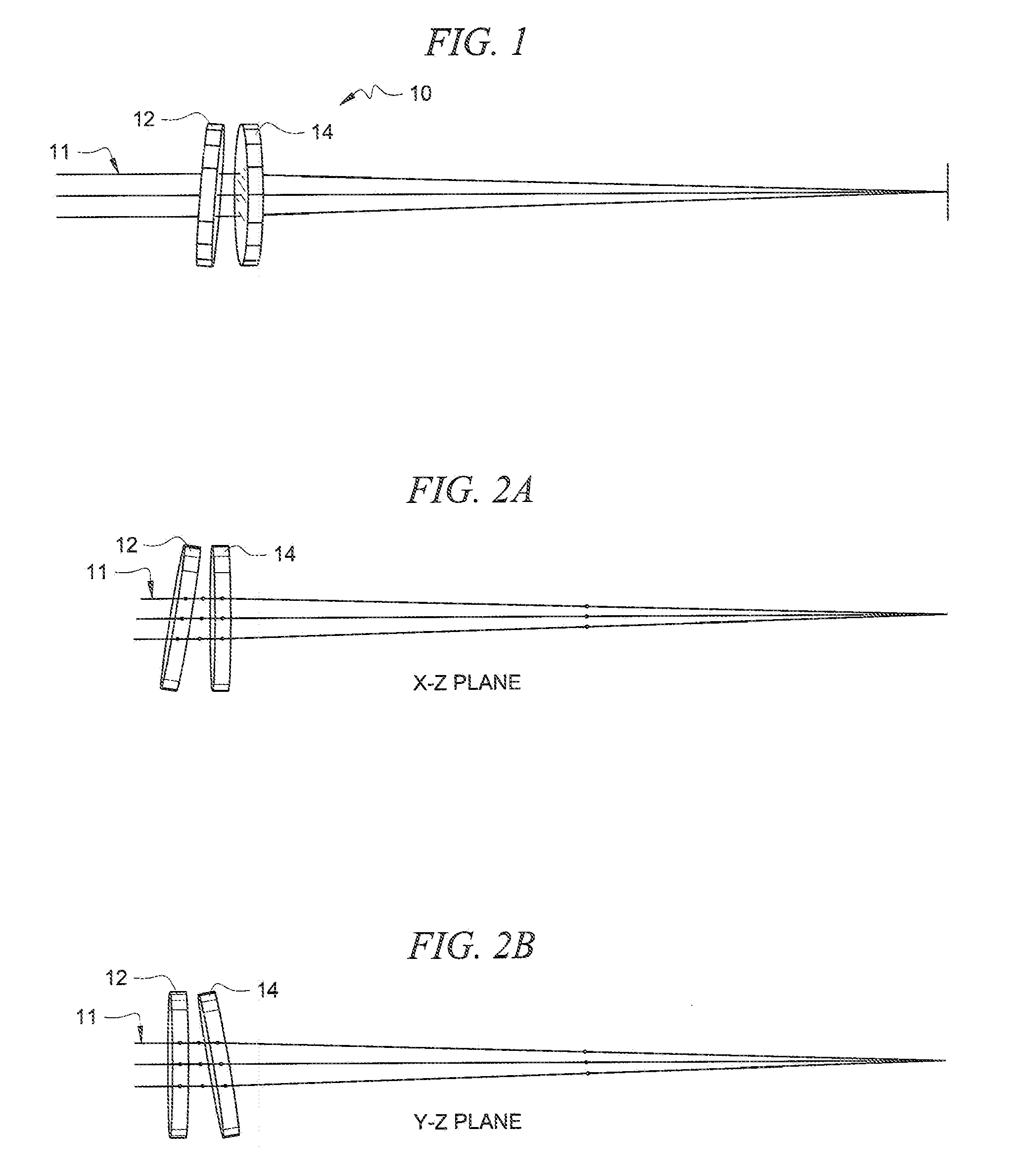
[0048]Referring now to FIG. 1, there it will be seen that the invention is denoted as a whole by the reference numeral 10.

[0049]Incoming laser beam 11 passes through a pair of inverted positive meniscus lenses 12 and 14. Each lens is mounted to a galvanometer to tilt each lens perpendicular to one another to displace the focus laser spot from the original optical axis. The preferred optical material is the highest possible index material for the desired laser wavelength. Having a high index allows the thickness of the lenses to be as thin as possible to minimize optical aberrations and minimize the inertia on the galvo.

[0050]In FIG. 2A lens 12 is tilted about the Y axis to displace the focused laser beam in a controlled manner along the X axis from the original optical axis.

[0051]In FIG. 2B, lens 14 is tilted about the X axis to displace the focused laser beam in a controlled manner along the Y axis from the original optical axis.

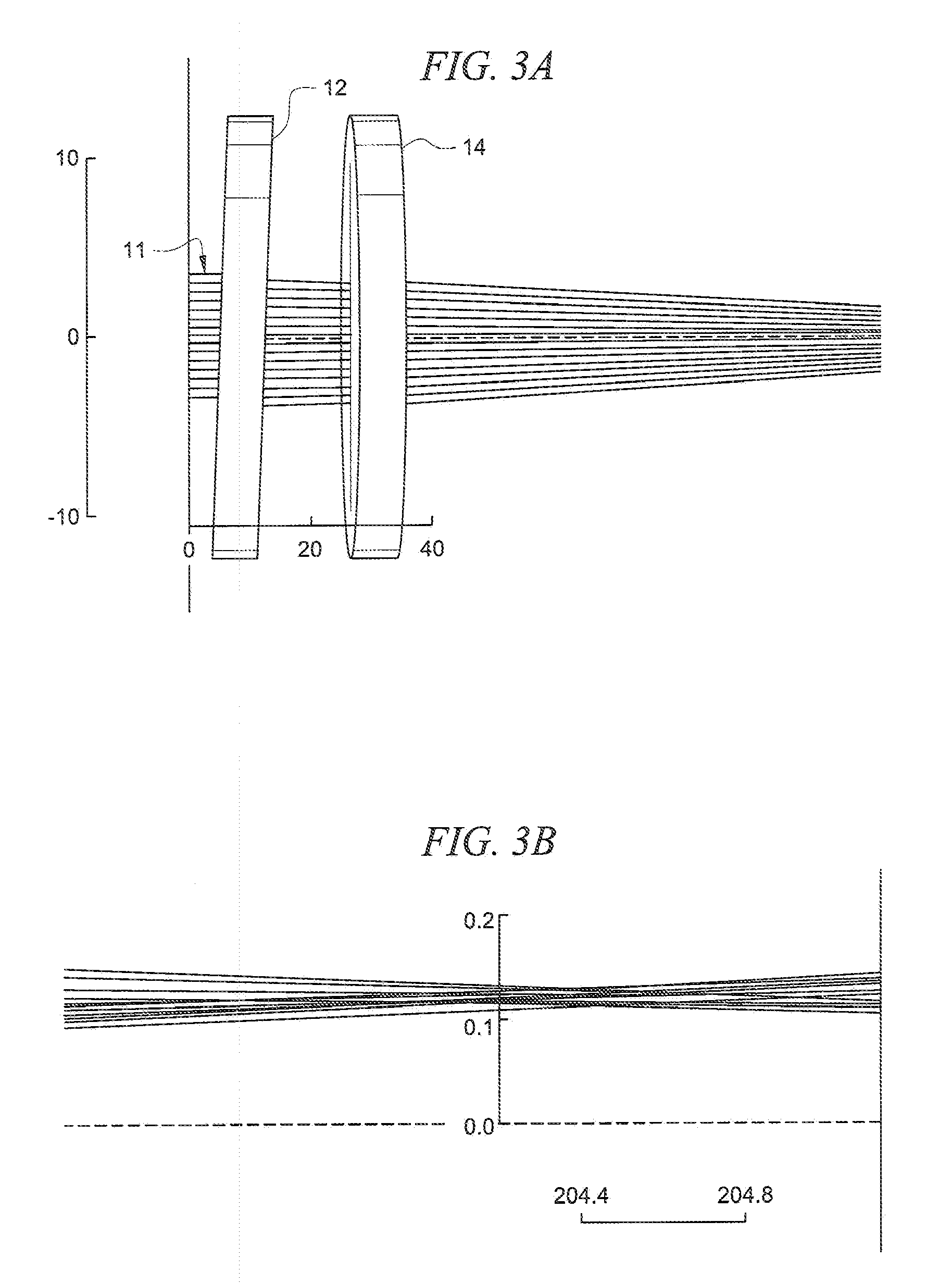
[0052]An amplified ray trace of the X-Z plane as ligh...

second embodiment

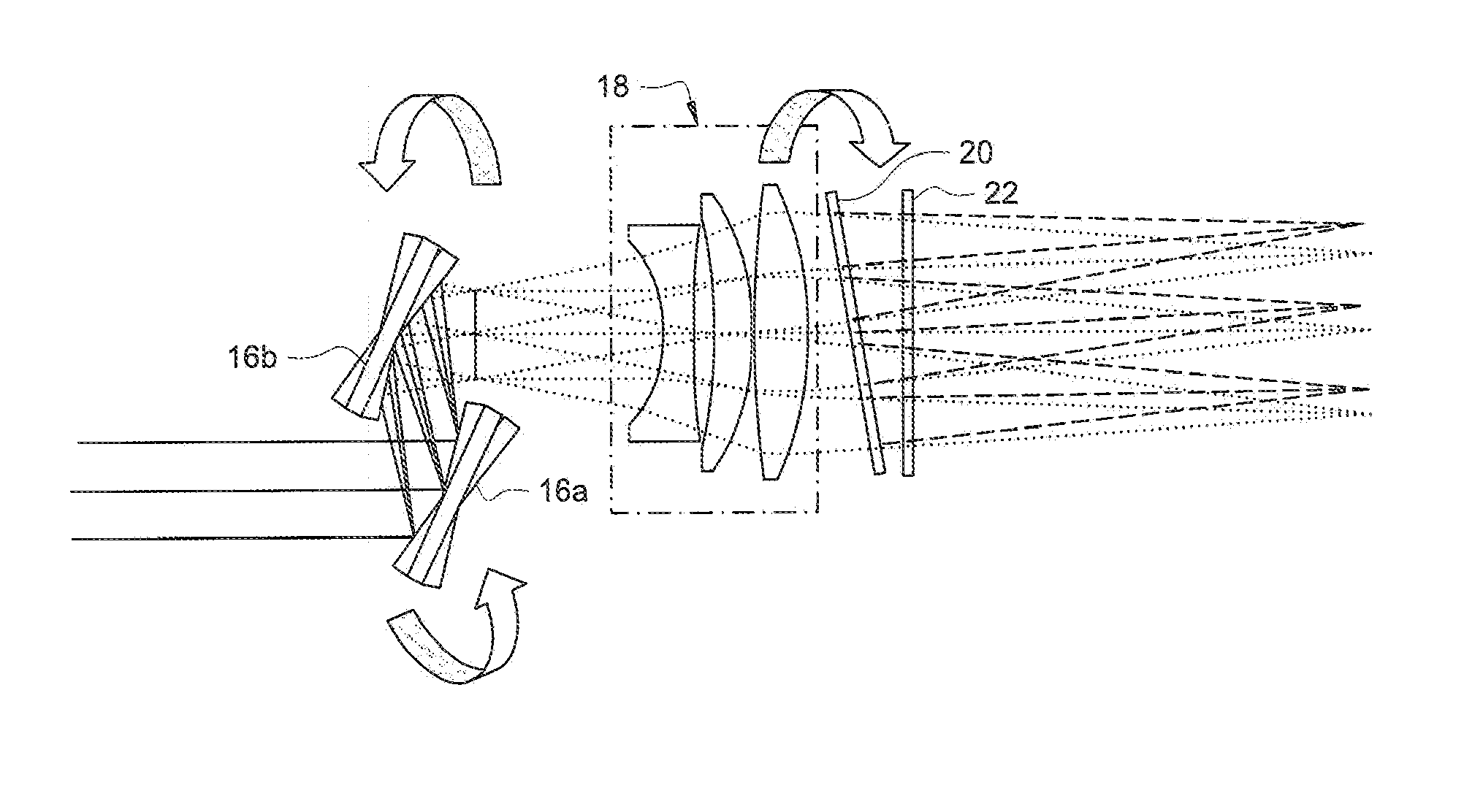
[0056]FIGS. 4A and 4B depict a second embodiment for displacing a focused laser beam from an optical axis. A laser beam enters a galvo scanner device that includes first and second galvo mirrors 16a, 16b. The beam is reflected from first galvo mirror 16a onto second galvo mirror 16b. From second galvo mirror 16b, the beam passes through F-theta lens 18 which typically includes three (3) lens elements as depicted in the drawing surrounded by a dashed rectangle. The beam exits F-theta lens 18 and passes through a pair of parallel plates 20, 22, each of which is mounted to a galvanometer. The parallel plate galvanometers are orientated orthogonally to one another so that the beam can be offset from the optical axis in a controlled way. The offset of the beam is determined by the angle of the plate, its thickness and the index of refraction of the plate. The dashed lines at the focal point of the lens represent the original optical axis. FIG. 8A depicts the X-Z plane and FIG. 8B depicts...


PUM


Abstract

A focused laser beam having an optical axis passes through a first lens mounted to a first galvanometer and a second lens mounted to a second galvanometer. The first galvanometer is adapted to tilt the first lens about a X axis and the second galvanometer is adapted to tilt the second lens about a Y axis. This displaces the focused laser beam in a controlled manner from the optical axis to enable laser machining of very precise geometric features over a large processing window. In a preferred embodiment, the first and second lenses are a pair of inverted positive meniscus lenses, of high index of refraction material.

Description

BACKGROUND OF THE INVENTION[0001]1. Field of the Invention[0002]This invention relates to optical scanning devices used for laser machining. More particularly, it relates to a high precision laser hole drilling and controlled material removal of geometries of less than 500 microns.[0003]2. Description of the Prior Art[0004]Galvanometer scanners have been used for nearly three (3) decades for laser material processing. They are most commonly used for laser marking. They have less utility in fine machining applications, in particular drilling precision holes and features below 250 microns, because their positional accuracy is limited below such threshold. Non-galvo-based approaches are limited to circular features and tend to be more optically and mechanically complex. Galvanometer-based systems are the simplest and least expensive way to direct a focused laser beam over a wide area. Nevertheless, they lack the “localized” precision for finite features over a large field.[0005]Thus th...

Claims


Application Information

Patent Timeline
IPC IPC(8): G02B26/08
CPCG02B26/105G02B26/101
Inventor SCAGGS, MICHAEL J.SCHOELZEL, THOMAS
Owner COHERENT INC
Why Eureka
Try Eureka