

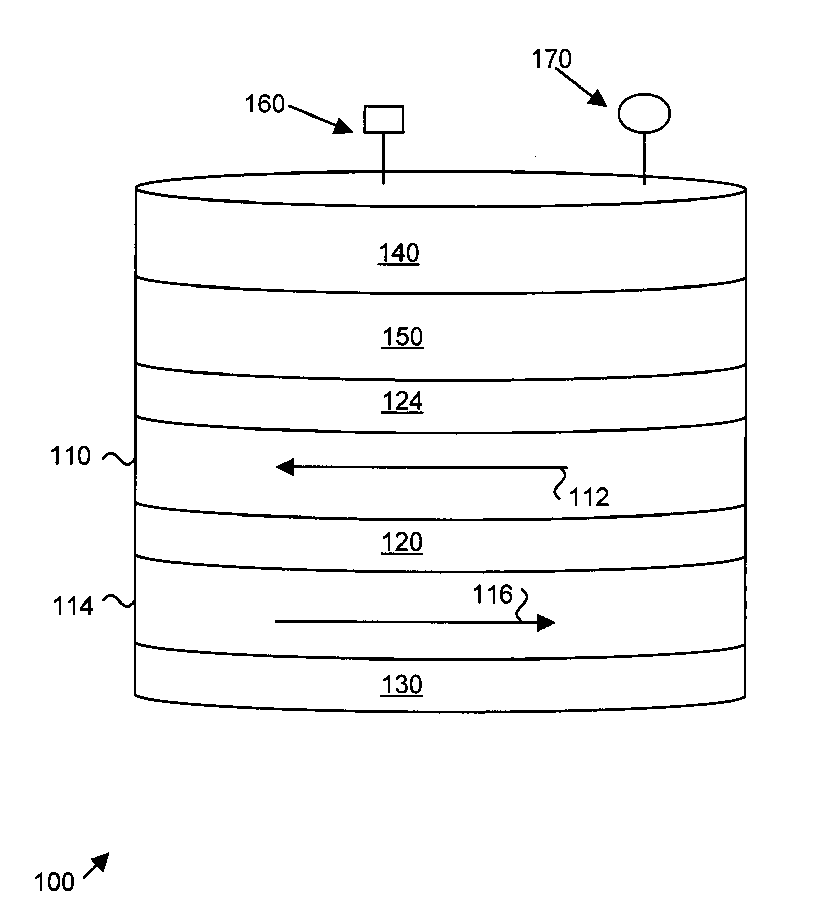
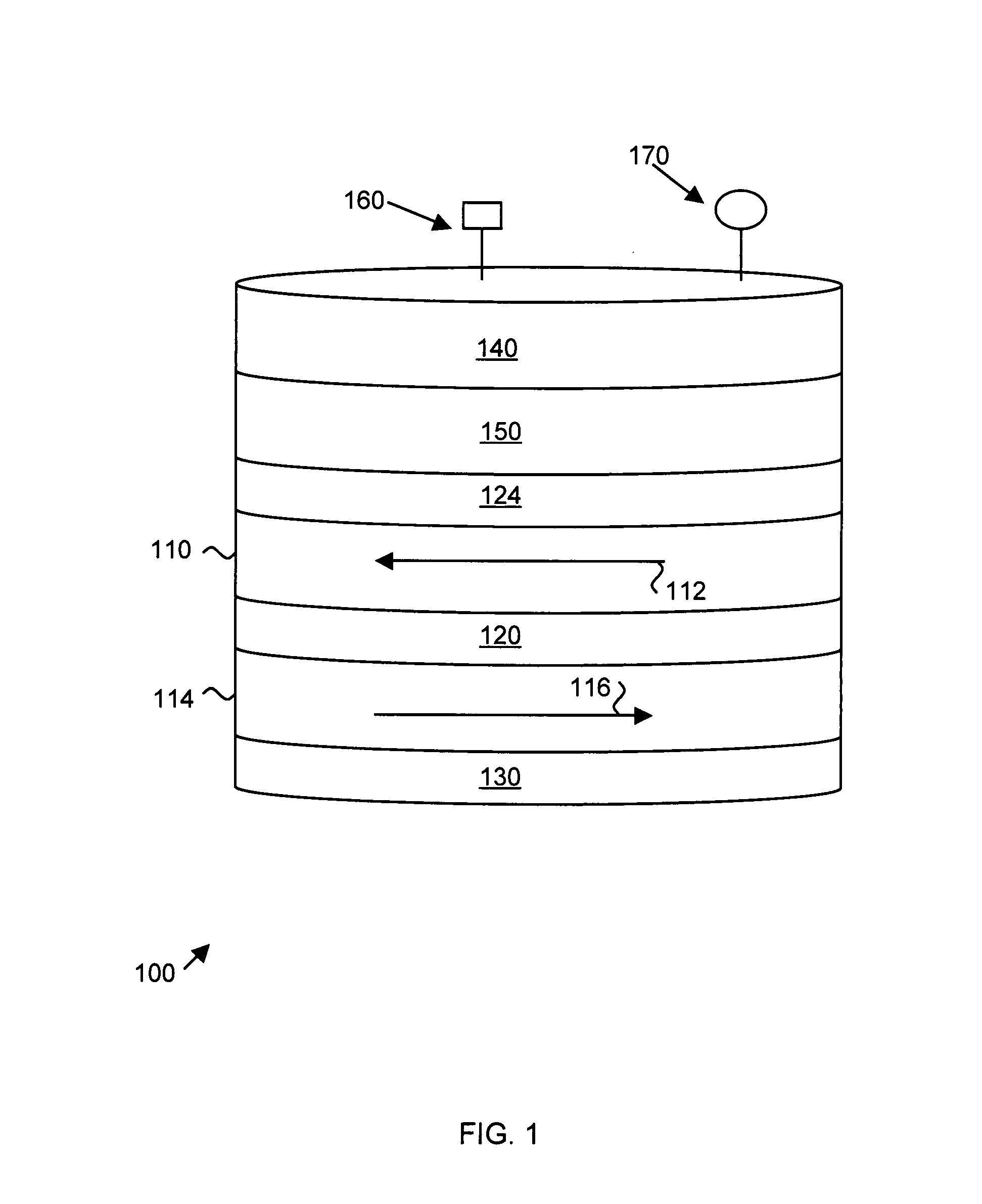
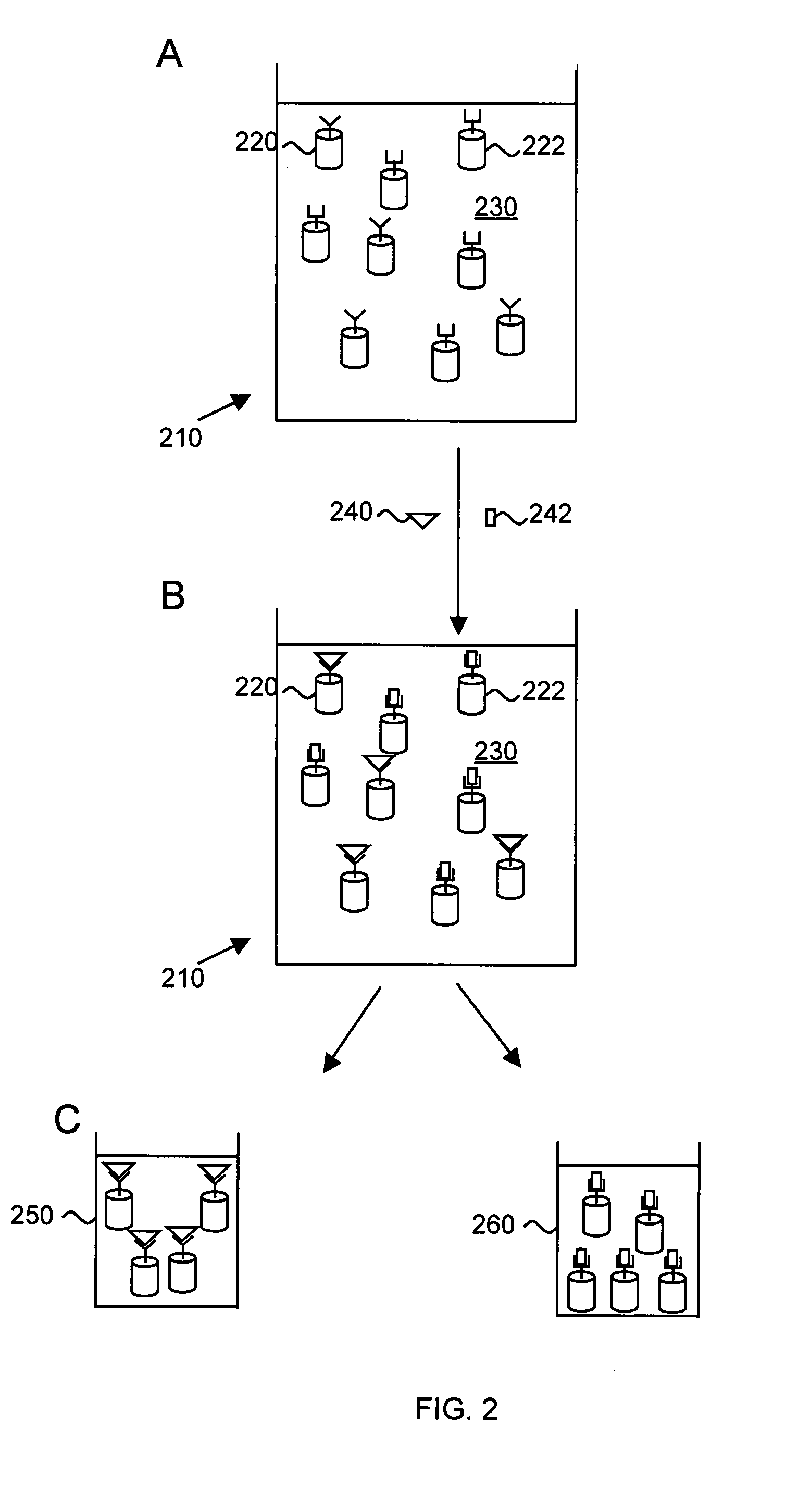
Synthetic antiferromagnetic nanoparticles
a nanoparticle and antiferromagnetic technology, applied in the field of detection of agents, can solve the problems of increasing the size of single grain superparamagnetic particles, affecting the detection efficiency of agents,
- Summary
- Abstract
- Description
- Claims
- Application Information
AI Technical Summary
Benefits of technology
Problems solved by technology
Method used
Image

Examples
examples
Direct Physical Fabrication of Synthetic Antiferromagnetic Nanoparticles
[0026]Nanoparticle fabrication began with vacuum coating of the substrate with a chemically etchable release layer of copper. A thin buffer layer of tantalum was also deposited to prevent oxidation of the Cu during subsequent resist bakes. All metal layers were deposited, at rates near 0.1 nm / sec, in a load locked vacuum system wherein a 1 keV, 10 mA xenon ion beam was directed at carousel-mounted targets at an operating pressure of 2×10⁻⁴ Torr. Next, a layer of polymethylglutarimide (PMGI) undercut resist (MicroChem) was spin coated onto the metal release layer and baked at 200° C. for 5 minutes. A layer of polymethyl methacrylate resist, PMMA, (MicroResistTechnology, 75 k MW), was then spin coated onto the wafer and baked at 140° C. for 5 minutes. The thickness of each resist layer was adjusted to accommodate stamp dimensions and particle thickness. The templates were then formed in the PMMA resist using therm...
PUM
| Property | Measurement | Unit |
|---|---|---|
| total thickness | aaaaa | aaaaa |
| total thickness | aaaaa | aaaaa |
| thickness | aaaaa | aaaaa |
Abstract
Description
Claims
Application Information