
Artificial Vascular Prosthesis

a prosthesis and artificial heart technology, applied in the field of vascular grafts, can solve the problems of multiple and severe complications, low kidney function, and death, and achieve the effect of reducing the risk of complications

Inactive Publication Date: 2008-08-28
NICAST LTD
View PDF14 Cites 27 Cited by
  • Summary
  • Abstract
  • Description
  • Claims
  • Application Information

AI Technical Summary

Benefits of technology

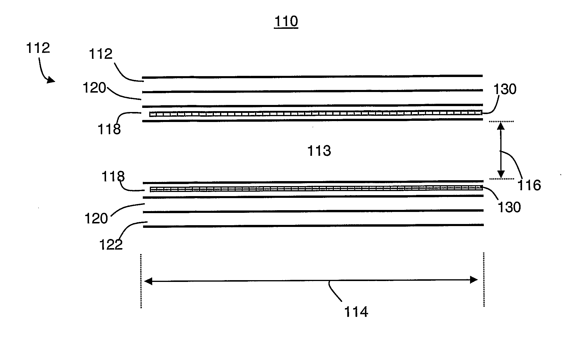
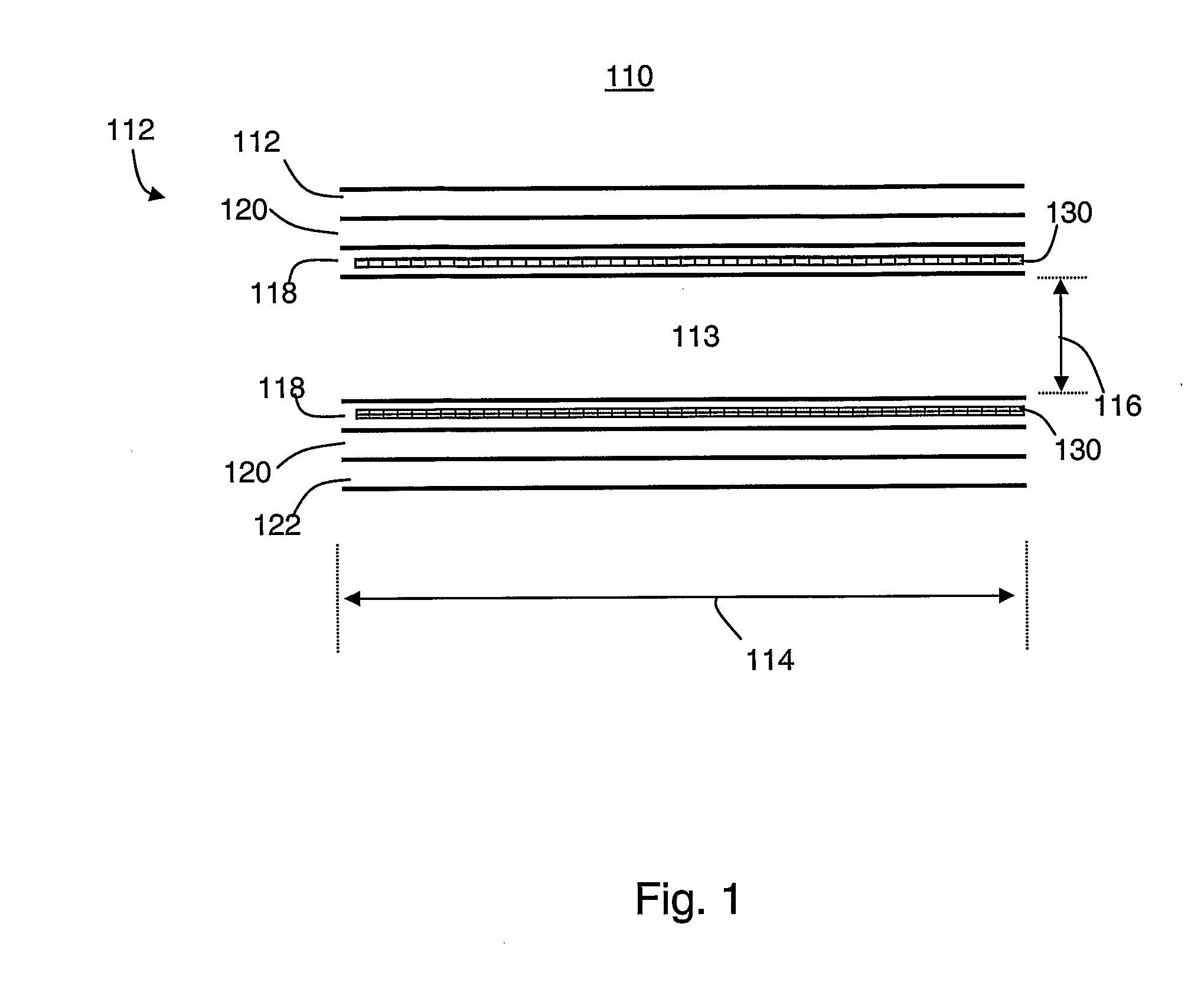
"The present invention provides a vascular prosthesis with superior self-sealing capabilities. The prosthesis has a tubular structure with at least two layers, wherein at least one layer includes a thrombogenic agent. The method of fabricating the prosthesis involves depositing a first material onto a template to form a first layer, depositing a second material composed of a thrombogenic agent onto the first layer to form the vascular prosthesis. The prosthesis can be used as a vascular access graft for dialysis patients. The thrombogenic agent can be coated upon or impregnated within the non-inner layer of the at least two layers. The tubular structure can be sized and dimensioned for use as a vascular access graft. A support structure can be embedded in the tubular structure. The thrombogenic agent can be selected from a group consisting of platelet activating factor, collagen, fibrin, factor V, factor IX, antiphospholipid antibody, copper, or platinum. Reinforcing fibers can be embedded in the tubular structure. The thrombogenic agent can be coated upon the reinforcing fibers. The technical effects of the invention include improved self-sealing capabilities, reduced risk of thrombosis, and improved patent text control."

Problems solved by technology

At this point, the kidney function is so low that without dialysis or kidney transplantation, complications are multiple and severe, and death will occur from accumulation of fluids and waste products in the body.
Additionally, ePTFE grafts take 10-15 minutes to achieve hemostasis following puncture for hemodialysis.
Another disadvantage with ePTFE vascular prostheses is suture-hole bleeding.
Although LeMaitre Vascular claims that these devices minimize suture hole bleeding, at present, clinical data demonstrating superior performance of these devices is unavailable.

Method used


Image

  • Artificial Vascular Prosthesis
  • Artificial Vascular Prosthesis
  • Artificial Vascular Prosthesis

Examples


example 1

A Two Layer Graft

[0123]A vascular prosthesis 6 mm in diameter and 200 mm in length was manufactured. A rod with 6 mm in diameter and 300 mm in length was used as a mandrel, and its central 200 mm portion was coated at ambient temperature, 24° C. Pump productivity was 3 ml / h.

[0124]CarboSil 20 polyuurethane solution was used to form both the inner layer and the outer layer, the thickness of which was 80 μm and 720 μm respectively, hence the total wall thickness was 800 μm. In the inner layer, the viscosity of the solution was 450 cP and the conductivity was 0.45 μS, and in the outer layer, the viscosity was 680 cP and the conductivity 1.8 μS. The graft was removed from the mandrel, rinsed repeatedly in deionized water, dried and sterilized.

Results

[0125]The mechanical parameters of the graft according to ISO 7198:1998 (E), were: general porosity of 68%, kinking diameter of 30 mm and dynamic compliance of 9%.

example 2

The Effect of Solution Viscosity

[0126]A vascular prosthesis 6 mm in diameter and 200 mm in length was manufactured as described in Example 1, however for both inner layer and outer layer equal solution viscosity of 450 cP and equal conductivity of 0.45 μS was used. In addition, the pump productivity was increased to 5 ml / h.

Results

[0127]The above changes lead to a slightly higher value of general porosity but lower anti-kinking strength and compliance. The mechanical parameters of the graft according to the ISO were: general porosity of 70%, kinking diameter of 35 mm and dynamic compliance of 8%.

example 3

The Effect of a Predetermined Fiber Orientation

[0128]A vascular prosthesis 6 mm in diameter and 200 mm in length was manufactured, as in Example 2, with the outer layer being formed from fibers placed in transverse (polar) orientation, for enhancing the radial strength of the graft. In addition, the thickness of the outer layer was 520 μm, hence total wall thickness reduced to 600 μm.

Results

[0129]The above changes lead to improvement of both antikinking resistance and dynamic compliance, without scarifying the general porosity. The mechanical parameters of the graft according to the ISO were: general porosity of 70%, kinking diameter of 32 mm and dynamic compliance of 10%.


PUM


Abstract

A vascular prosthesis having a tubular structure is provided. The tubular structure is fabricated from at least two layers wherein at least one layer includes a thrombogenic agent.

Description

FIELD AND BACKGROUND OF THE INVENTION[0001]The present invention relates to a vascular prosthesis having self sealing capabilities and, more particularly, to vascular grafts fabricated from non-woven materials impregnated or coated with thrombogenic agents.[0002]End-stage renal disease (ESRD) occurs when the kidneys are no longer able to function at a level that is necessary for day to day life. It usually occurs as chronic renal failure worsens to the point where kidney function is less than 10% of normal. At this point, the kidney function is so low that without dialysis or kidney transplantation, complications are multiple and severe, and death will occur from accumulation of fluids and waste products in the body. The most common cause of ESRD in the U.S. is diabetes.[0003]Patients suffering from end stage renal disease typically undergo artificial dialysis of their blood, as a substitute to kidney transplantation. In the U.S. more than 400,000 people are on long-term dialysis an...

Claims


Application Information

Patent Timeline
Patent Type & Authority Applications(United States)
IPC IPC(8): A61F2/06
CPCA61F2250/0067A61F2/06
Inventor SHALEV, ALONDUBSON, ALEXANDER
Owner NICAST LTD
Learn More