Micro-Cavity Measuring Equipment and Method Based on Double Optical Fiber Coupling

a technology of optical fiber coupling and micro-cavity, which is applied in the direction of mechanical measuring arrangement, instruments, and using mechanical means, etc., can solve the problems of insufficient minimum diameter and depth, inability to obtain inside information of holes, and inability to use probes for excessive vibration

Inactive Publication Date: 2008-09-04
TAN JIUBIN +1
View PDF3 Cites 13 Cited by
  • Summary
  • Abstract
  • Description
  • Claims
  • Application Information

AI Technical Summary

Benefits of technology

[0038]In this invention, the reflected light signal can be enhanced through the effluent optical fiber, the minimum dimension of a micro-cavity to be measured can go up to 0.01 mm for the limit imposed by the optical fiber core, and the measuring depth aspect ratio is up to 50:1 because of the use of the sight and transmitter with double optical fiber coupling and associated length measurement device.
[0039]Another advantage of the measuring equipment is that the signals from CCD camera is the changes in position of the light spot when the double optical fiber coupling unit gets in contact with the wall of a micro-cavity, so the invention can be used to measure the vertical or tilted wall of an object.
[0040]And what's more, the measuring equipment can independently be used in other equipments, for example, a coordinate measuring machine. The equipment can be used together with other equipments to fulfill the task of measuring micro-cavities and the positions of micro-cavities in a particular part or compound.

Problems solved by technology

How to precisely measure the dimensions of a micro-cavity is a new problem for the measurement field and the solution of this problem involves many key techniques, and what we have to do is to minimize the conflicts among accuracy, range and depth.
In comparison with the contact method, non-contact optical methods can be used to fulfil the task of measuring holes of small diameter at higher accuracy, but these methods can be used to measure the surface of a hole only at a very shallow depth and cannot be used to obtain the inside information of a hole because of the bulky size of an optical system.
But the measurement accuracy is subject to the influence of contaminants, and the probe may be broken for excessive vibration.
So the minimum diameter and depth achievable with this method can not be large enough, even when a twin-stylus or high-aspect-ratio probe is used.
However, it is almost impossible to use these methods to measure a micro-hole with a diameter of less than 1 mm.
However, the image from the CCD camera is so weak that it is not suitable for image processing because most of the light enters the micro-sphere through the optical fiber can not enter the optic imaging system.
Consequently the measurement depth is very shallow because of the shading effect of the wall of the micro-hole, and the method is no longer usable if the aspect-ratio is greater than 10:1.
When the micro-sphere get in contact with the wall of the micro-hole, the image from the CCD camera will not be changed because the depth of field of the optical system is fixed, and so, the sensitivity and accuracy achievable with this method are not good enough, either.

Method used


Image

  • Micro-Cavity Measuring Equipment and Method Based on Double Optical Fiber Coupling
  • Micro-Cavity Measuring Equipment and Method Based on Double Optical Fiber Coupling
  • Micro-Cavity Measuring Equipment and Method Based on Double Optical Fiber Coupling

Examples


Embodiment Construction

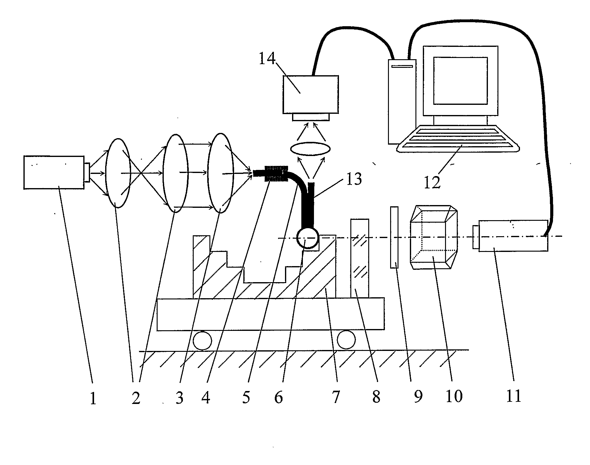
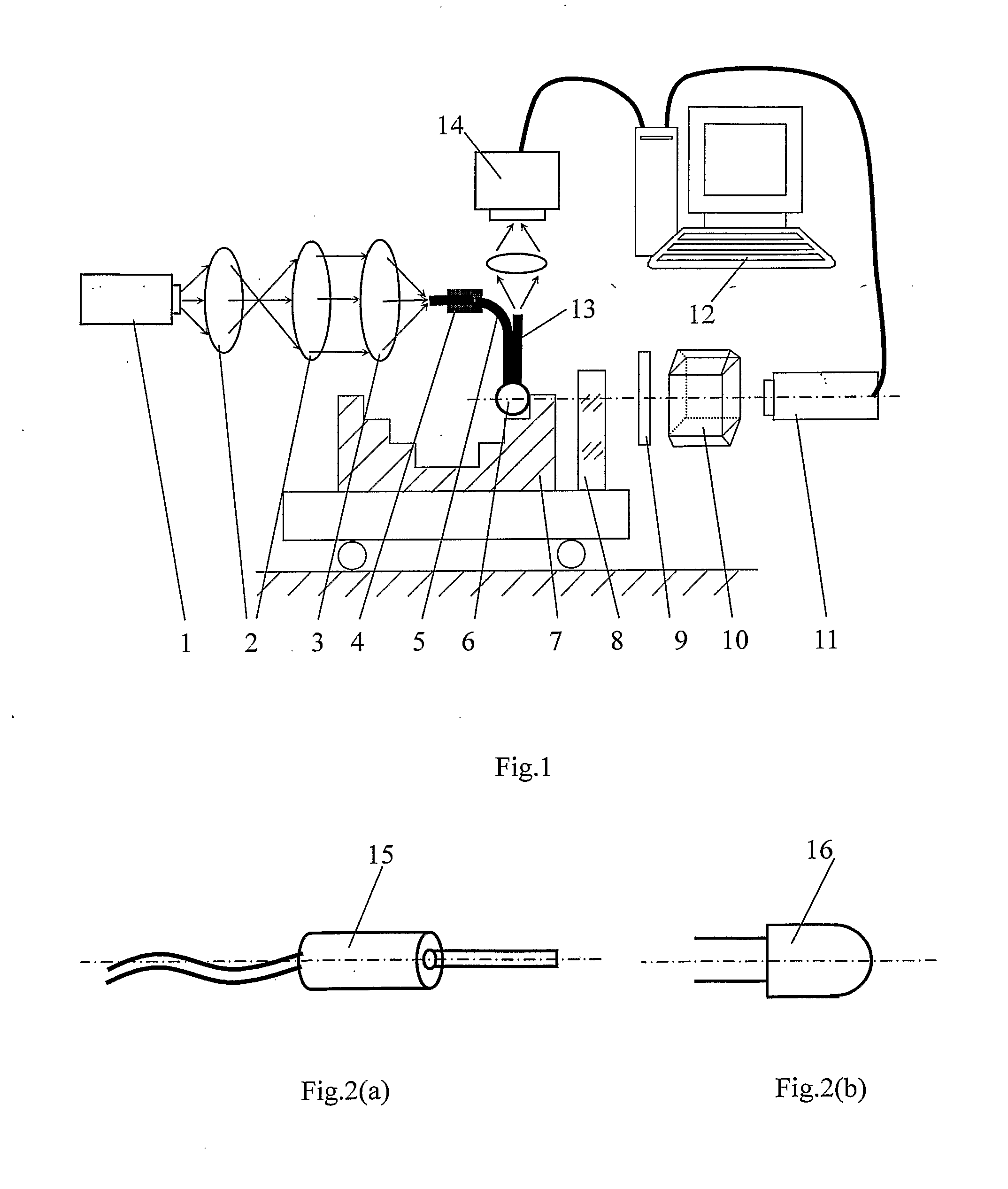
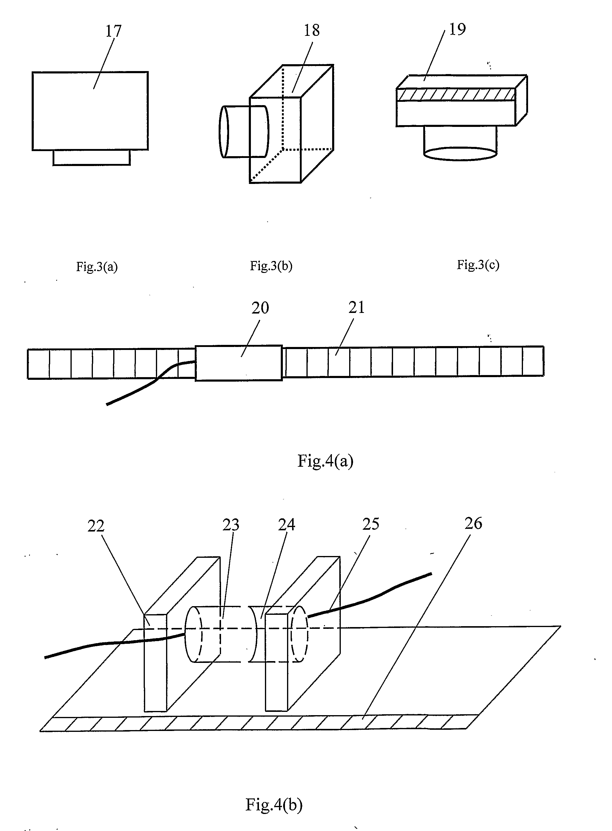
[0052]As shown in FIGS. 1˜4, the measuring equipment consists of laser (1), beam collimator and enlarger (2), optical fiber coupling lens (3), fixing block (4), incident optical fiber (5), coupler (6), worktable (7), reflector (8), λ / 4 wave slice (9), polarized beam splitter (10), double frequency laser interferometer (11), computer (12), effluent optical fiber (13), and CCD camera (14). The laser coupling unit consists of laser (1), beam collimator and enlarger (2), optical fiber coupling lens (3), and fixing block (4), and in which, laser (1), beam collimator and enlarger (2), optical fiber coupling lens (3), and one end of incident optical fiber (5) are coaxial. The double optical fiber coupling unit consists of incident optical fiber (5) in the form of an orthogonal arc, coupler (6), and effluent optical fiber (13) in the form of a straight line, and the ends of incident and effluent optical fibers are fixed on coupler (6) while the other ends are coplanar. Coupler (6) is used a...


PUM


Abstract

A micro-cavity measuring equipment based on double optical fiber coupling includes a sight and transmitter, a controller, and a length measuring device. The equipment detects small changes in the position of an object with respect to a probe from a moment when the sight and transmitter starts working to another moment when the sight and transmitter stops working. The controller has a program to automatically control the whole measuring process. The measuring equipment is characterized in that the sight and transmitter consists of a laser unit, a data collecting and processing unit, and a double optical fiber coupling unit with its ends of incident and effluent optical fibers fixed on a coupler. A micro-cavity measuring method based on double optical fiber coupling consists of the following steps: inserting the probe into the micro-cavity and moving it in the measuring direction; sending signals to the length measuring device by the sight and transmitter to cause the length measuring device to record the corresponding position of the probe when the probe is contact with the sides of the micro-cavity; and then calculating the dimensions of the micro-cavity.

Description

FIELD OF THE INVENTION[0001]This invention relates to one type of measuring equipment and method as described in claims 1 and 8 above, which can be used for measurement of irregular micro-cavities and “sub-macro” micro-cavities in particular, in addition to conventional contact measurement.BACKGROUND OF THE INVENTION[0002]The number of parts with micro-cavities increases with the development of hi-tech industries, such as aerospace industry, and auto industry. The proper measurement of these micro-cavities becomes a “bottleneck” for further development of these hi-tech industries, and this justifies the necessity of developing a good type of micro-cavity measuring equipment and method.[0003]How to precisely measure the dimensions of a micro-cavity is a new problem for the measurement field and the solution of this problem involves many key techniques, and what we have to do is to minimize the conflicts among accuracy, range and depth. A wider range can be achieved at a deeper depth ...

Claims


Application Information

Patent Timeline
Patent Type & Authority Applications(United States)
IPC IPC(8): G01B5/004
CPCG01B11/007G01B5/201G01B11/12G01B11/2408
Inventor TAN, JIU BINCUI, JIWEN
Owner TAN JIUBIN
Why Eureka
Try Eureka