Solvent Evaporator

Inactive Publication Date: 2008-09-04
VAPORTEC
View PDF14 Cites 24 Cited by
  • Summary
  • Abstract
  • Description
  • Claims
  • Application Information

AI Technical Summary

Benefits of technology

[0010]The high speed rotation allows the surface area of the solution in the receptacle to be maximised whilst using a standard sized / shaped receptacle, and is preferably also sufficient to prevent bumping. The vertical orientation of the receptacle also contributes to maximising the surface area, whilst allowing easy exchange of receptacles.
[0085]Alternatively or additionally in this development, the method may further comprise the step of controlling the pressure in the receptacle to prevent phase change from liquid to solid as the solution is dispensed.

Problems solved by technology

While rotation evaporators of this type offer rapid evaporation and have therefore been widely adopted in Chemistry and Biology laboratories they have limitations.
Furthermore, the solution must be placed in a suitable receptacle for evaporation, typically a round bottom distillation flask; such a receptacle is impractical for future storage or transportation of concentrated or dry products.
Commonly this transfer process is non trivial requiring multiple distillations and scraping of dry or semi-dry products from the distillation flask, thus requiring significant laboratory staffing time and resulting in loss of product and the potential for contamination.
However, such evaporators are slow batch processes and as such are unsuitable for incorporation into the modern automated synthesis and purification processes.
Centrifugal evaporators of this type are also relatively inconvenient to load / unload.
Centrifugal evaporators of this type are further limited in that when solutions are dried into solids, the solids take the form of hard pellets in the bottom of the receptacle.
It is not only difficult to evaporate the final molecules of solvent from these pellets but the pellets themselves are very difficult to redissolve.

Method used


Image

  • Solvent Evaporator
  • Solvent Evaporator
  • Solvent Evaporator

Examples


Embodiment Construction

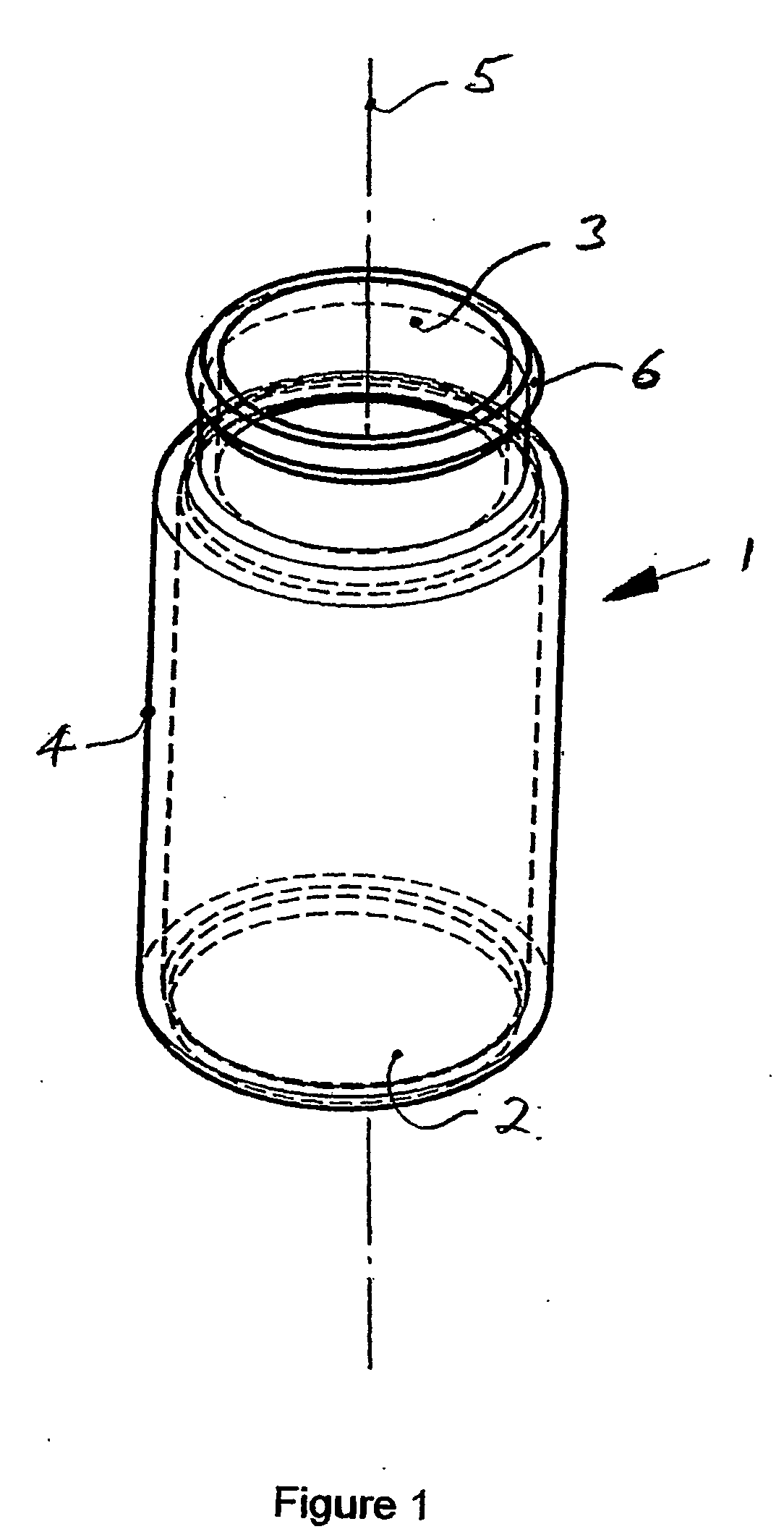
[0104]With reference to FIG. 1, a vaporising receptacle 1 has a substantially cylindrical portion 4 the axis of this cylindrical portion is labelled 5. The receptacle is closed at the lower end 2. An aperture 3 in the upper end is concentric with the cylindrical portion 4, having a diameter smaller than the internal diameter of the cylindrical portion 4. A feature 6 is provided for fixing a closure by, for example, manual operation, to the receptacle once the evaporation process is complete. The vaporising receptacle is manufactured from an impervious inert material so that it will not contaminate the sample or suffer corrosion; the material also allows transmission of infrared radiation. A suitable vaporising receptacle is readily available, being a 20 ml scintillation vial manufactured from borosilicate glass material.

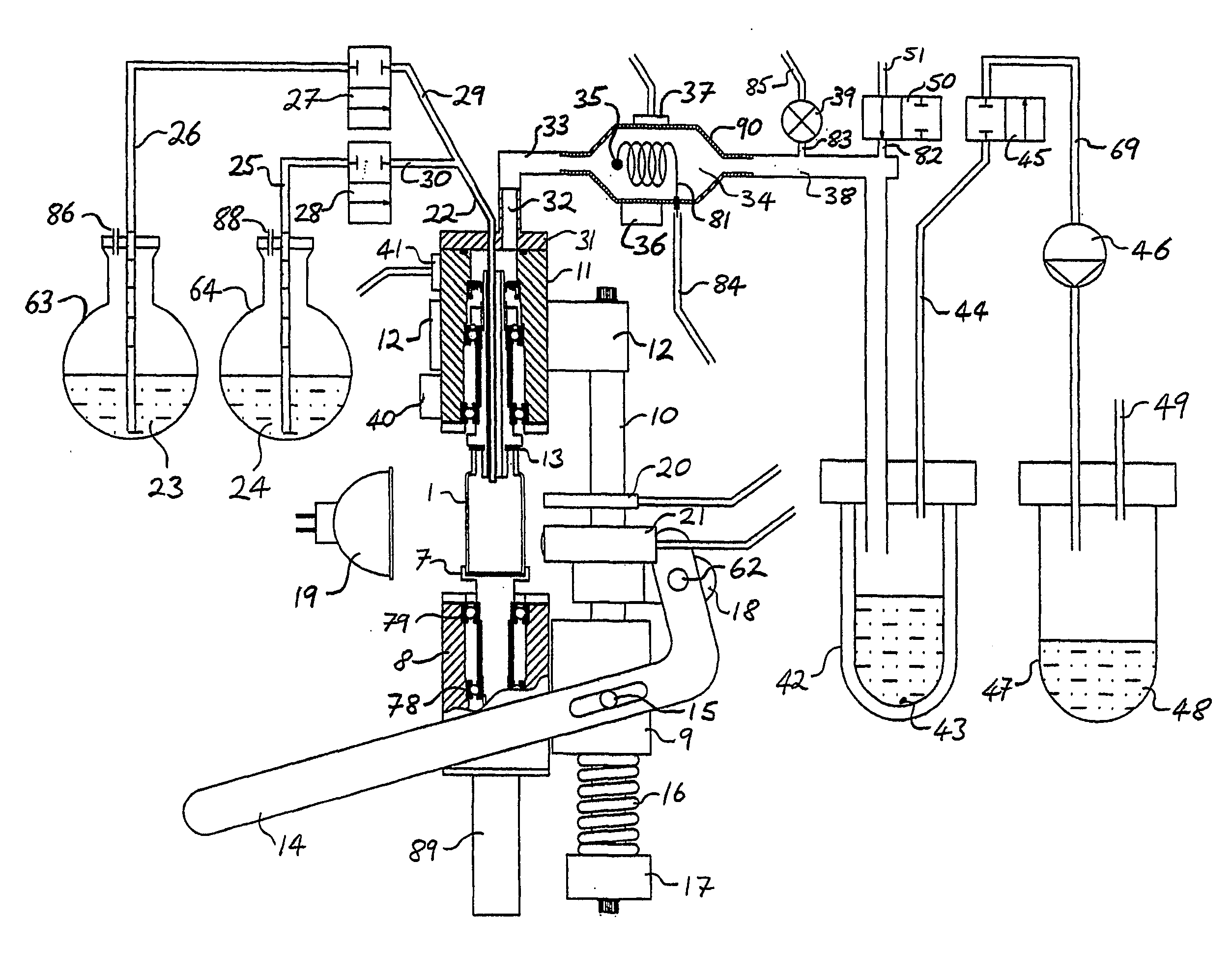
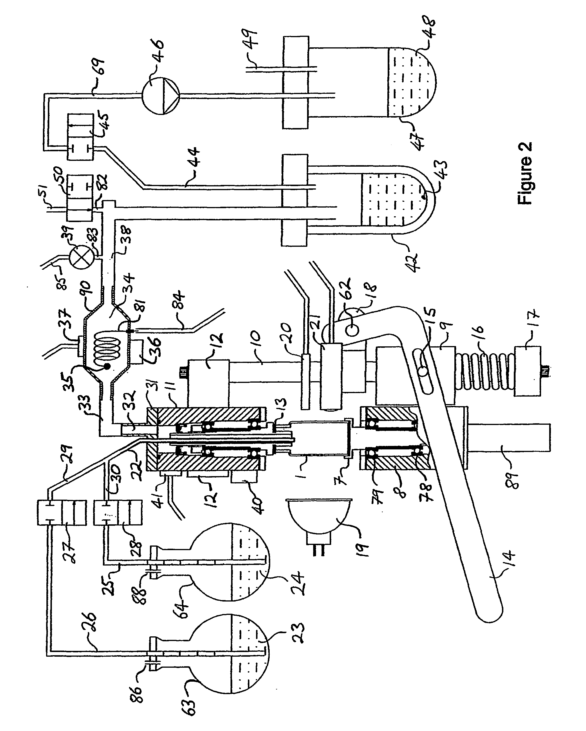
[0105]Referring to FIGS. 2 and 6, in the embodiment shown in FIG. 2, the vaporising receptacle 1 is supported on the end of a shaft 7, which is mounted for rotation ...


PUM


Abstract

An apparatus for concentrating solutions in a vaporising receptacle (1) is provided wherein the receptacle (1) has a mouth (3), and the axis of the receptacle is perpendicular to the mouth. The apparatus comprises: support means (7) for supporting the vaporising receptacle with the mouth of the receptacle uppermost and the axis substantially vertical; rotation means (89) being operable to rotate the vaporising receptacle at high speed substantially about the axis; means (13) for sealing the vaporising receptacle to the apparatus; a vacuum pump (46) to reduce the pressure within the vaporising receptacle; means (22) for dispensing into the vaporising receptacle a solution to be concentrated; sensing means (21) to measure the temperature of the solution within the vaporising receptacle; heating means (19, 99) to apply heat to the solution within the vaporising receptacle; a control and regulating unit (75) for controlling or regulating at least one of said rotation means, said vacuum pump, said dispensing means, said sensing means and said heating means. The invention allows low pressure evaporation in regularly sized and shaped receptacles without bumping, and is also easy to use. A corresponding method is provided.

Description

FIELD OF THE INVENTION[0001]This invention relates to an apparatus and method for evaporating liquids, particularly, but not exclusively for the purposes of either increasing the concentration of a solution and / or for the complete removal of a solvent from a solution to leave a dry solid.BACKGROUND TO THE INVENTION[0002]In practice an apparatus for this purpose is known which is generally referred to as a rotation evaporator. An apparatus of this kind is disclosed in U.S. Pat. No. 2,797,747. The receptacle of this rotation evaporator, formed as a round bottomed distilling flask in borosilicate glass, is rotated about its axis by means of a motor during distillation and is connected via a rotary union to a condenser. A vacuum source, for example a diaphragm pump, is connected to the condenser. As a heating arrangement a so called heating bath is used, preferably having a liquid heat transfer medium that can be heated by means of an immersion heater.[0003]While rotation evaporators of...

Claims


Application Information

Patent Timeline
IPC IPC(8): B01D1/24B01D1/00B01D1/22B01D3/10B04B15/02B04B15/08G01N1/40
CPCB01D1/222G01N2001/4027B01D3/10
Inventor GUTHRIE, DUNCAN
Owner VAPORTEC
Why Eureka
Try Eureka