Sputtering apparatus

a technology of sputtering apparatus and sputtering chamber, which is applied in the direction of vacuum evaporation coating, electrolysis components, coatings, etc., can solve the problems of short maintenance cycle, difficult to ensure the distribution of film thickness, and dark spots on the surface of electrodes, so as to achieve high use efficiency of the first and second targets

Active Publication Date: 2008-09-04
ULVAC INC
View PDF2 Cites 4 Cited by
  • Summary
  • Abstract
  • Description
  • Claims
  • Application Information

AI Technical Summary

Benefits of technology

[0022]The present invention has been made to solve the above-described problems and is intended to improve the usage efficiency of targets.
[0028]According to the sputtering apparatus of the present invention, the erosion area is large even if the first and second magnet members are held relatively stationary with respect to the first and second targets without being moved. Thus, a mechanism or device to move the first and second magnet members is not required, thereby simplifying the structure of the apparatus. In addition, 100 gauss is converted to 10 mT, wherein T (tesla) is the SI unit.
[0030]Since the strength distribution of the horizontal magnetic field components formed above the surfaces of the first and second targets is so narrow that the absolute value thereof is 100 gauss or less, the surfaces of the first and second targets are sputtered uniformly. Accordingly, in each portion of the first and second targets, the film thickness decreases uniformly so the usage efficiency of the first and second targets is high.

Problems solved by technology

However, since films formed with the vapor deposition method have poor adhesion to the organic layer, problems occur, such problems including the generation of dark spots and the exfoliation of electrodes due to the long-term drive.
Moreover, from the viewpoint of productivity, the vapor deposition method has problems, including the difficulty in ensuring a film thickness distribution in a large area due to a point evaporation source, and a short maintenance cycle due to the deterioration of an evaporation boat and the difficulty in continuously supplying evaporation materials.
However, in a parallel plate type sputtering method in which an object to be film-formed is made to face the surface of a target, when an aluminum upper electrode is formed on the organic layer, problems occur in the driving test of the organic EL devices.
Such problems include luminescence starting voltage becoming extremely high or no light being emitted.
These problems occur because in the sputtering method, the charged particles (Ar ions, secondary electrons, recoil Ar) in plasma and the sputtered particles with a high kinetic energy are irradiated upon the organic layer, thereby destroying the interface between the organic layers and thus failing to favorably inject electrons.

Method used


Image

  • Sputtering apparatus
  • Sputtering apparatus
  • Sputtering apparatus

Examples


embodiments

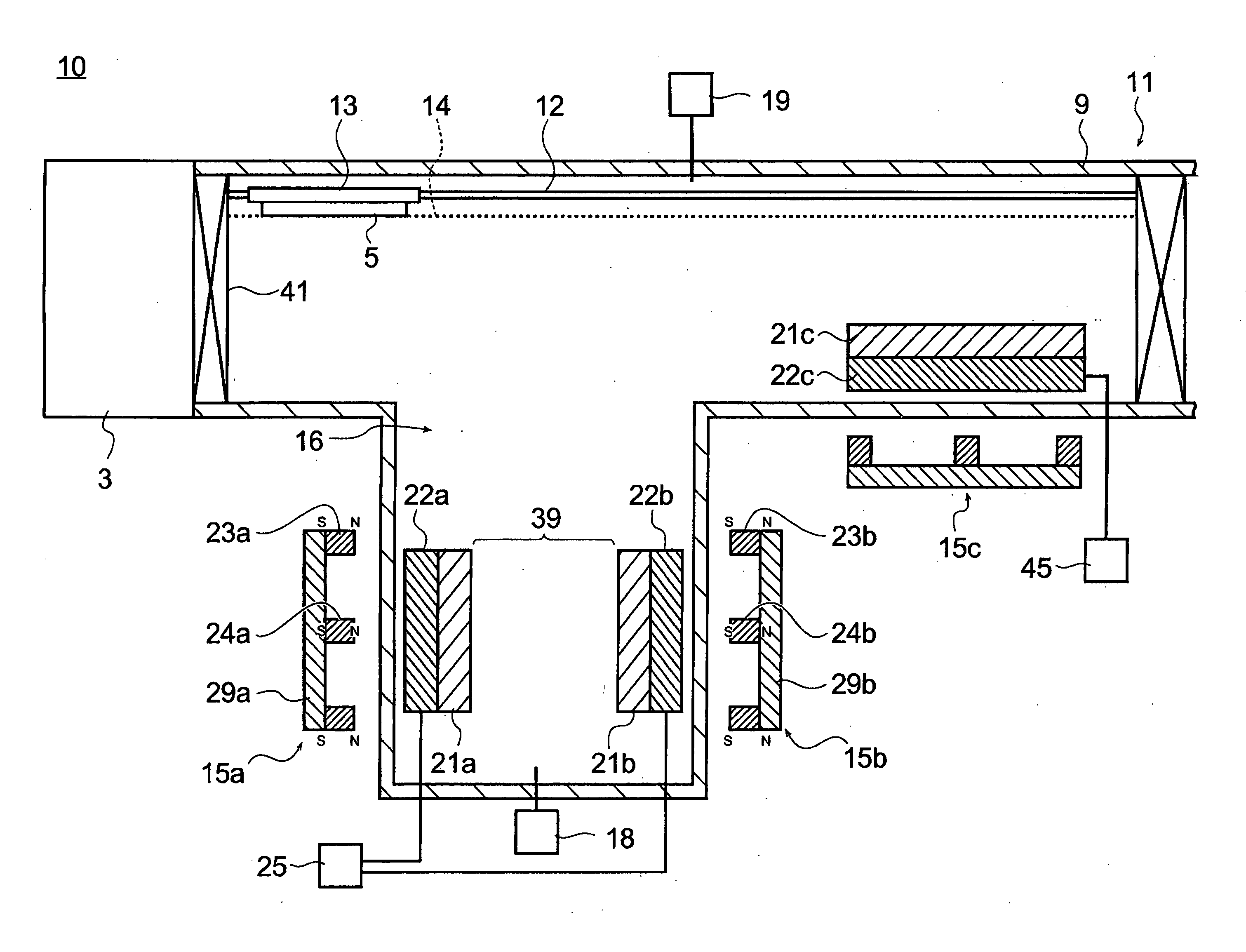
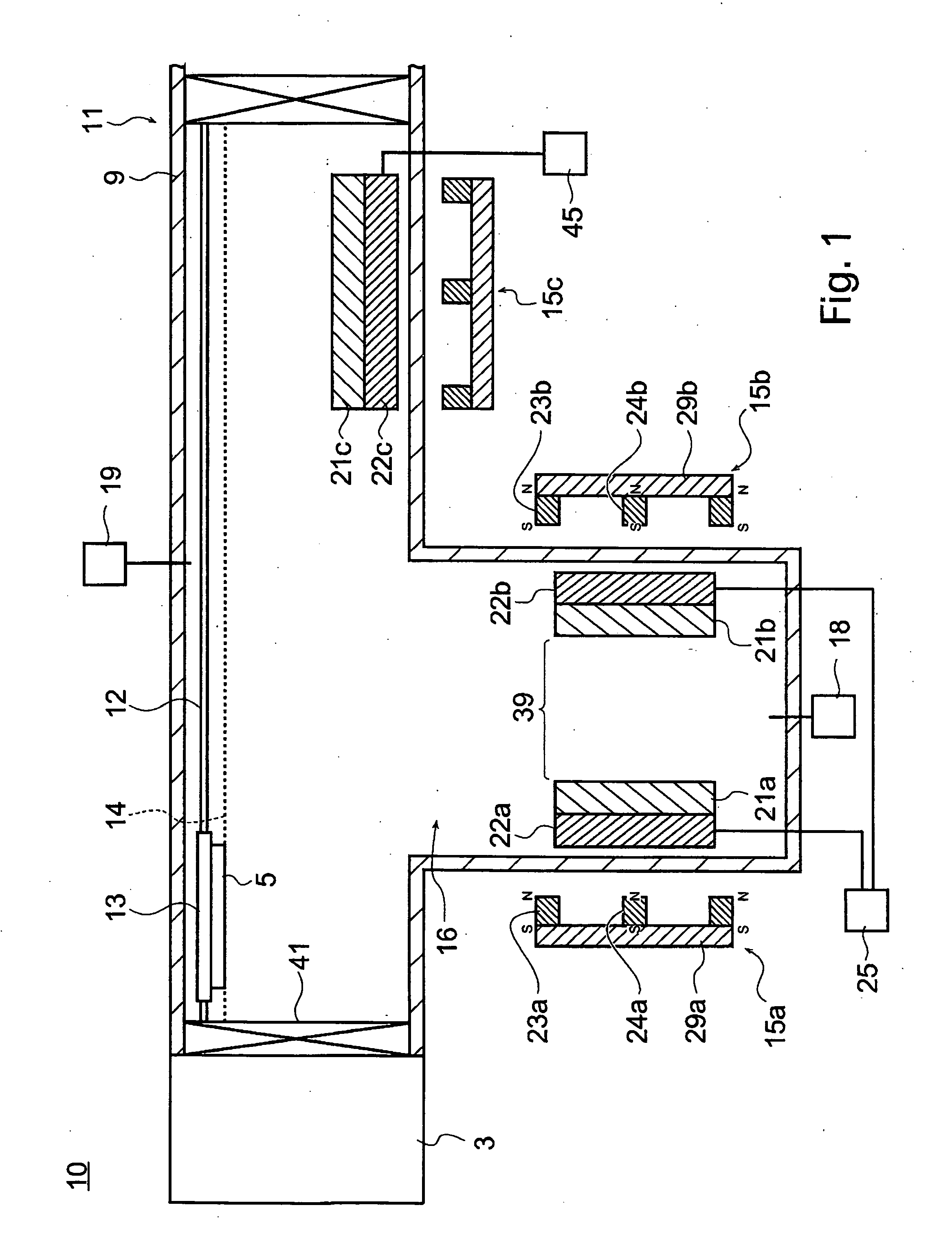
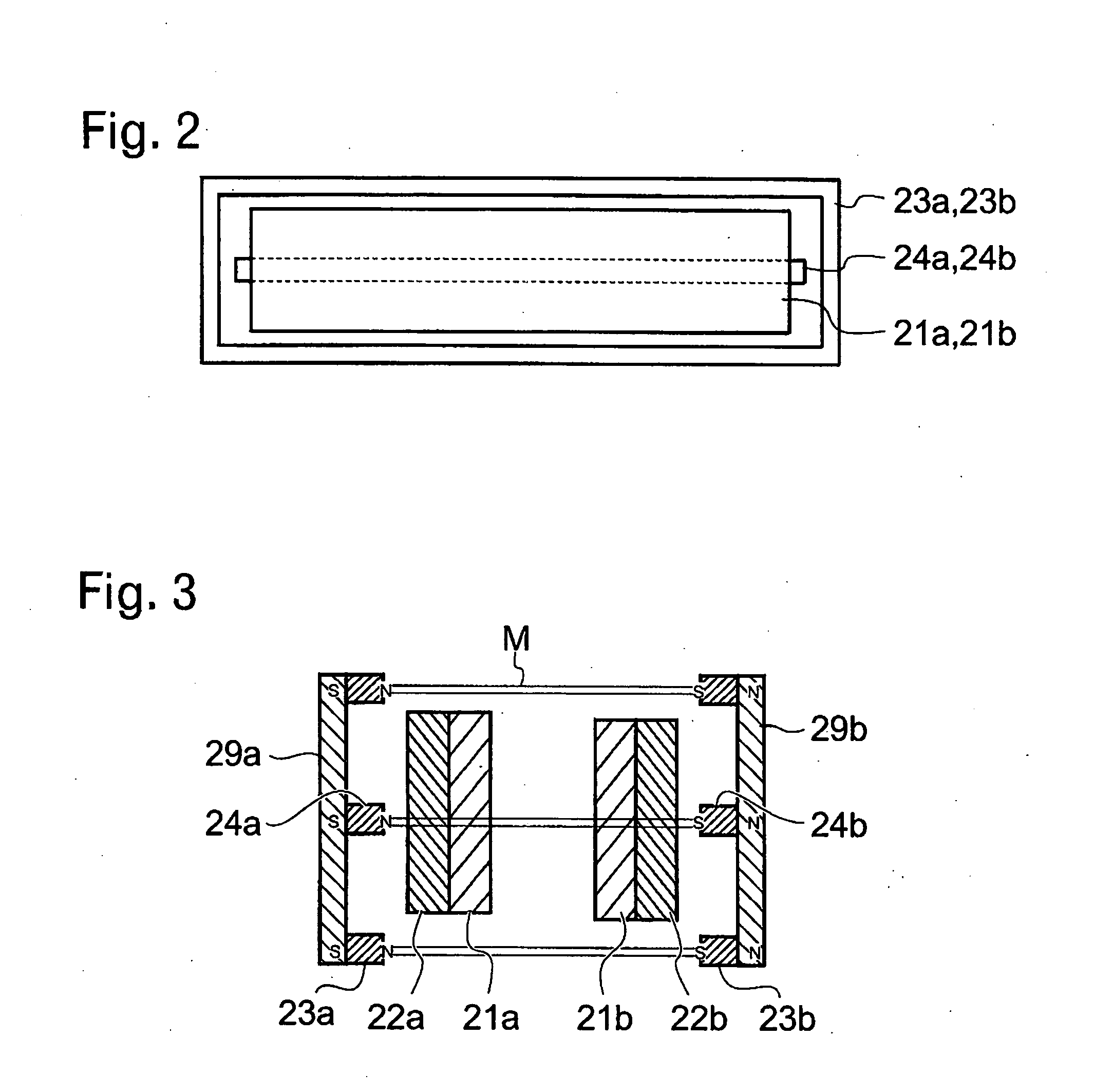
[0090]As shown in FIG. 5, a magnetic field forming device 15, wherein a magnet member 24 is arranged inside a ring magnet 23, is arranged so that the N pole of the ring magnet 23 and the N pole of the magnet member 24 are faced toward the rear surface of a target; and among the magnetic fields formed on the surface of the target, the strength of vertical magnetic field components perpendicular to the surface of the target and the strength of horizontal magnetic field components parallel to the surface of the target are measured.

[0091]The measurement points of the vertical magnetic field component and horizontal magnetic field component are located at three locations; i.e., positions (A-A, C-C) 50 mm inner side from the edge on the outer peripheral side of both shorter sides of the ring magnet 23, respectively, and a center position (B-B) in the longitudinal direction, and the measurement is made at every 10 mm along the width direction of the ring magnet 23 (FIG. 5).

[0092]In additio...


PUM

PropertyMeasurementUnit
magnetic fieldaaaaaaaaaa
vertical magnetic fieldaaaaaaaaaa
strength of horizontal magnetic fieldaaaaaaaaaa

Abstract

A sputtering apparatus with high usage efficiency of a target is provided. A sputtering apparatus of the present invention includes first and second ring magnets, first and second magnet members arranged inside a ring of the first and second ring magnets, wherein in the first and second ring magnets and the first and second magnet members, magnetic poles with the same magnetism are faced toward the rear surface of a first and a second targets. Thus, in the rear surface of the first and second targets, the magnetic poles with the same polarity are adjacently arranged, and the absolute value of the strength of horizontal magnetic field components formed in the surfaces of the first and second targets becomes small and the strength distribution becomes narrow, and the strength of vertical magnetic field components becomes uniform; and consequently, a non-erosion portion is not produced in the first and second targets.

Description

[0001]The present invention is a Continuation of International Application No. PCT / JP2006 / 319963 filed Oct. 5, 2006, which claims priority to Japan Patent Document No. 2005-303491, filed on Oct. 18, 2005. The entire disclosures of the prior applications are hereby incorporated by reference herein in their entireties.BACKGROUND[0002]The present invention generally relates to sputtering apparatuses.[0003]Recently, there has been increasing interest in organic EL element as a display device.[0004]FIG. 12 is a schematic cross-sectional view for illustrating the structure of an organic EL device 201.[0005]This organic EL device 201 has a lower electrode 214, organic layers 217, 218, and an upper electrode 219 laminated in this order on a substrate 211; and light emission occurs within the organic layers 217, 218 or at the interface between the organic layers 217, 218 if a voltage is applied to between the upper electrode 219 and the lower electrode 214. If the upper electrode 219 is comp...

Claims


Application Information

Patent Timeline
Patent Type & Authority Applications(United States)
IPC IPC(8): C23C14/00
CPCC23C14/35H01J37/3405H01L51/56H01L51/5203H01J37/3452H01J37/3408H01J37/3417H01J37/345H01J37/347H01J37/3482H10K50/805H10K71/00C23C14/352
Inventor TAKASAWA, SATORUUKISHIMA, SADAYUKITANI, NORIAKIISHIBASHI, SATORU
Owner ULVAC INC
Why Eureka
Try Eureka