Laser apparatus

a laser and apparatus technology, applied in the field of laser apparatuses, can solve the problems of low efficiency of conversion to laser light, apparatus disclosed, and inability to produce coherent light with laser light, and achieve the effect of improving energy conversion efficiency

Inactive Publication Date: 2008-09-04
DENSO CORP
View PDF14 Cites 5 Cited by
  • Summary
  • Abstract
  • Description
  • Claims
  • Application Information

AI Technical Summary

Benefits of technology

[0008]In the above inequality, R1, R2 represent the first and second reflectivities, respectively, λ0 represents the wavelength of the excitation light, and FWHM represents a full width at half maximum of an absorption spectrum of the solid laser medium layer at the wavelength of the excitation light. From the above inequality, the top and bottom reflectors of the first reflector are formed so that the FWHM of the solid laser medium layer at the wavelength of the excitation light is greater than a resonance wavelength range of the surface-emitting laser device. In such an approach, the surface-emitting laser device can be prevented from lasing at a wavelength outside the FWHM of the solid laser medium layer. Thus, the laser apparatus has improved energy conversion efficiency.

Problems solved by technology

Therefore, the apparatus disclosed in JP-A-2004-134633 cannot be used as a laser light source to produce coherent light.
Therefore, efficiency of conversion to laser light is low so that the apparatus cannot achieve high power laser output.
Since the apparatus disclosed in US 20060083284 requires two laser devices, it is difficult to reduce its size.

Method used


Image

  • Laser apparatus
  • Laser apparatus
  • Laser apparatus

Examples


first embodiment

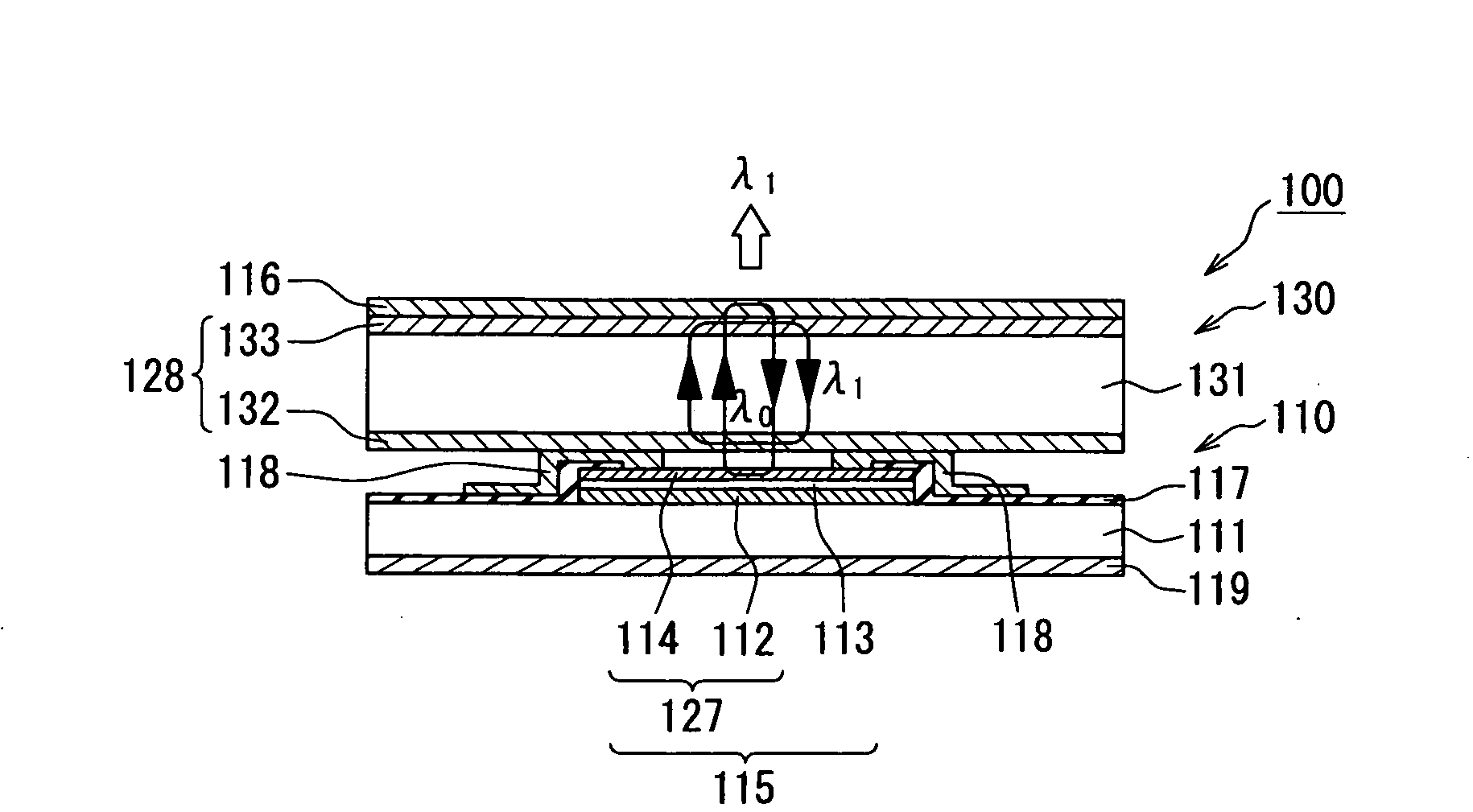
[0027]Referring to FIG. 1, a laser apparatus 100 according to a first embodiment of the present invention includes an excitation light generator 110 and a wavelength converter 130 having a solid laser media layer 131. The excitation light generator 110 outputs excitation (i.e., pump) light. The wavelength converter 130 receives the excitation light and outputs converted light with a wavelength different from that of the excitation light.

[0028]The excitation light generator 110 includes a surface-emitting laser device 115 formed on a semiconductor substrate 111. The surface-emitting laser device 115 includes a first reflector 127 and an active layer 113. The first reflector 127 includes a n-type bottom reflective layer 112 and a p-type top reflective layer 114 that are located on opposite sides of the active layer 113. The excitation light generator 110 further includes a second reflector 116. The surface-emitting laser device 115 and the second reflector 116 are located on opposite ...

second embodiment

[0067]A laser apparatus 101 according to a second embodiment of the present invention is described below with reference to FIG. 6. Differences between the laser apparatus 100, 101 are as follows.

[0068]As shown in FIG. 1, according to the laser apparatus 100 of the first embodiment, the semiconductor substrate 111 is located on a side of the bottom reflective layer 112 of the first reflector 127. Therefore, the surface-emitting laser device 115 emits the excitation light in a direction opposite to the semiconductor substrate 111. In contrast, as shown in FIG. 6, according to the laser apparatus 101 of the second embodiment, the semiconductor substrate 111 is located on a side of the top reflective layer 114 of the first reflector 127. Therefore, the surface-emitting laser device 115 emits the excitation light in a direction to the semiconductor substrate 111.

[0069]The excitation light emitted by the active layer 113 resonates between the bottom and top reflective layers 112, 114. Thu...

third embodiment

[0071]A laser apparatus 102 according to a third embodiment of the present invention is described below with reference to FIG. 7. Differences between the laser apparatus 100, 102 are as follows.

[0072]As can be seen by comparing FIG. 1 with FIG. 7, the laser apparatus 102 further includes a wavelength conversion element 134 that is disposed on the light-emitting surface of the solid laser medium layer 131. The bottom reflective layer 132 of the third reflector 128, the solid laser medium layer 131, the wavelength conversion element 134, the top reflective layer 133 of the third reflector 128, and the second reflector 116 are integrally stacked together in that order so that the laser apparatus 102 can be reduced in size.

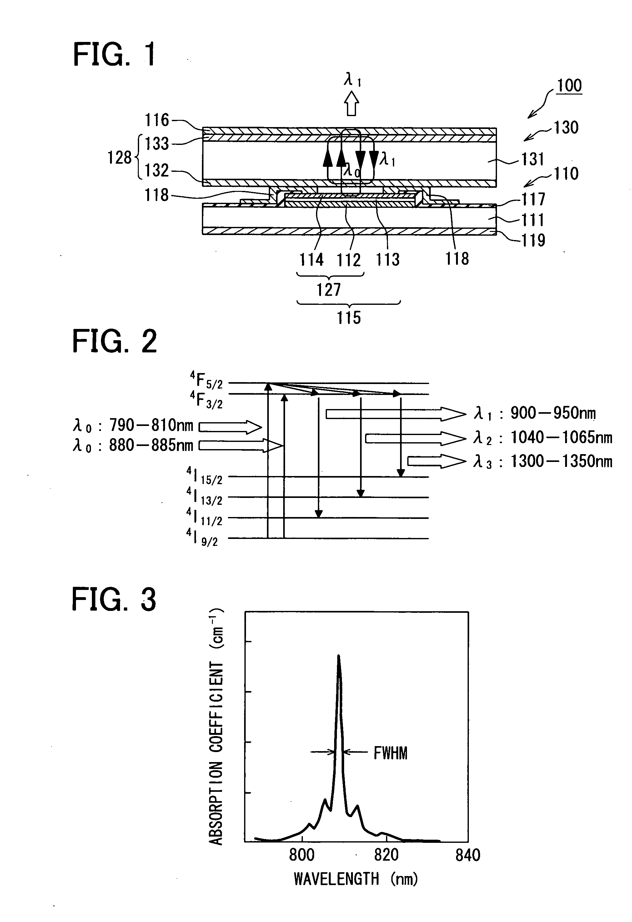
[0073]The solid laser medium layer 131 selectively converts the excitation light with the wavelength λ0 to the light with the wavelengths λ1-λ3. The wavelength conversion element 134 converts the light with the wavelengths λ1-λ3 to light with wavelengths different fro...


PUM


Abstract

A laser apparatus includes an excitation light generator for emitting excitation light and a wavelength converter including a solid laser medium for emitting laser light by converting a wavelength of the excitation light. The excitation light generator includes a surface-emitting laser having a first reflector with top and bottom reflectors and an active layer disposed between the top and bottom reflectors. The excitation light generator further includes a second reflector configured to highly reflect the excitation light. The solid laser medium is disposed between the surface-emitting laser device and the second reflector. Reflectivities of the top and bottom reflectors of the first reflector are set so that FWHM of the solid laser medium at the wavelength of the excitation light is greater than a resonance wavelength range of the surface-emitting laser device.

Description

CROSS REFERENCE TO RELATED APPLICATION[0001]This application is based on and incorporates herein by reference Japanese Patent Application No. 2007-51740 filed on Mar. 1, 2007.FIELD OF THE INVENTION[0002]The present invention relates to a laser apparatus for producing laser light by converting a wavelength of excitation light.BACKGROUND OF THE INVENTION[0003]As disclosed in JP-A-2004-134633, U.S. Pat. No. 6,879,618 corresponding to JP-A-2005-20002, or US 20060083284 corresponding to JP-A-2006-113591, an apparatus has been proposed that produces laser light by converting a wavelength of excitation light. In an apparatus disclosed in JP-A-2004-134633, a phosphor layer is excited by excitation light emitted by a surface-emitting laser to produce light having a different wavelength from that of the excitation light. In an apparatus disclosed in U.S. Pat. No. 6,879,618, an organic active layer of a vertical laser cavity structure is excited by excitation light emitted by an organic light-...

Claims


Application Information

Patent Timeline
Patent Type & Authority Applications(United States)
IPC IPC(8): H01S5/04H01S5/18
CPCH01S3/005H01S3/025H01S3/0604H01S3/0627H01S3/09415H01S5/423H01S3/2391H01S5/14H01S5/18305H01S5/18369H01S3/109
Inventor OTAKE, NOBUYUKIABE, KATSUNORI
Owner DENSO CORP
Why Eureka
Try Eureka