Electromagnetic Transmission/Reception System

a transmission/reception system and electromagnetic technology, applied in the field of electromagnetic transmission and reception systems, can solve the problems of thermal effects limited to laser diodes, conventional microwave sources that do not operate at sufficiently high frequency to efficiently produce radiation, and light sources that cannot be bright enough to produce radiation. , to achieve the effect of improving noise performance, stable coherent detection, and facilitating the generation of ultra-low noise signals

Inactive Publication Date: 2008-09-04
UNIVERSITY OF KENT
View PDF19 Cites 66 Cited by
  • Summary
  • Abstract
  • Description
  • Claims
  • Application Information

AI Technical Summary

Benefits of technology

[0017]In particular, the invention enables the implementation of a system able to generate ultra-low noise signals and to coherently receive such signals. The system has applications in a range of areas, for example for imaging (including radar type applications), communications and component testing/analysis. The invention is suitable for very high frequency signals, up to the THz range. For example, the output signal may have a frequency in the range 100 GHz to 30 THz, for example in the range 100 GHz to

Problems solved by technology

Until recently, bright sources of light and sensors have not been available for this frequency band.
Conventional microwave sources do not operate at sufficiently high frequency to efficiently produce radiation in the gap, whereas laser diode sources have been limited by thermal effects.
However, in such a system, which wo

Method used


Image

  • Electromagnetic Transmission/Reception System
  • Electromagnetic Transmission/Reception System
  • Electromagnetic Transmission/Reception System

Examples


Embodiment Construction

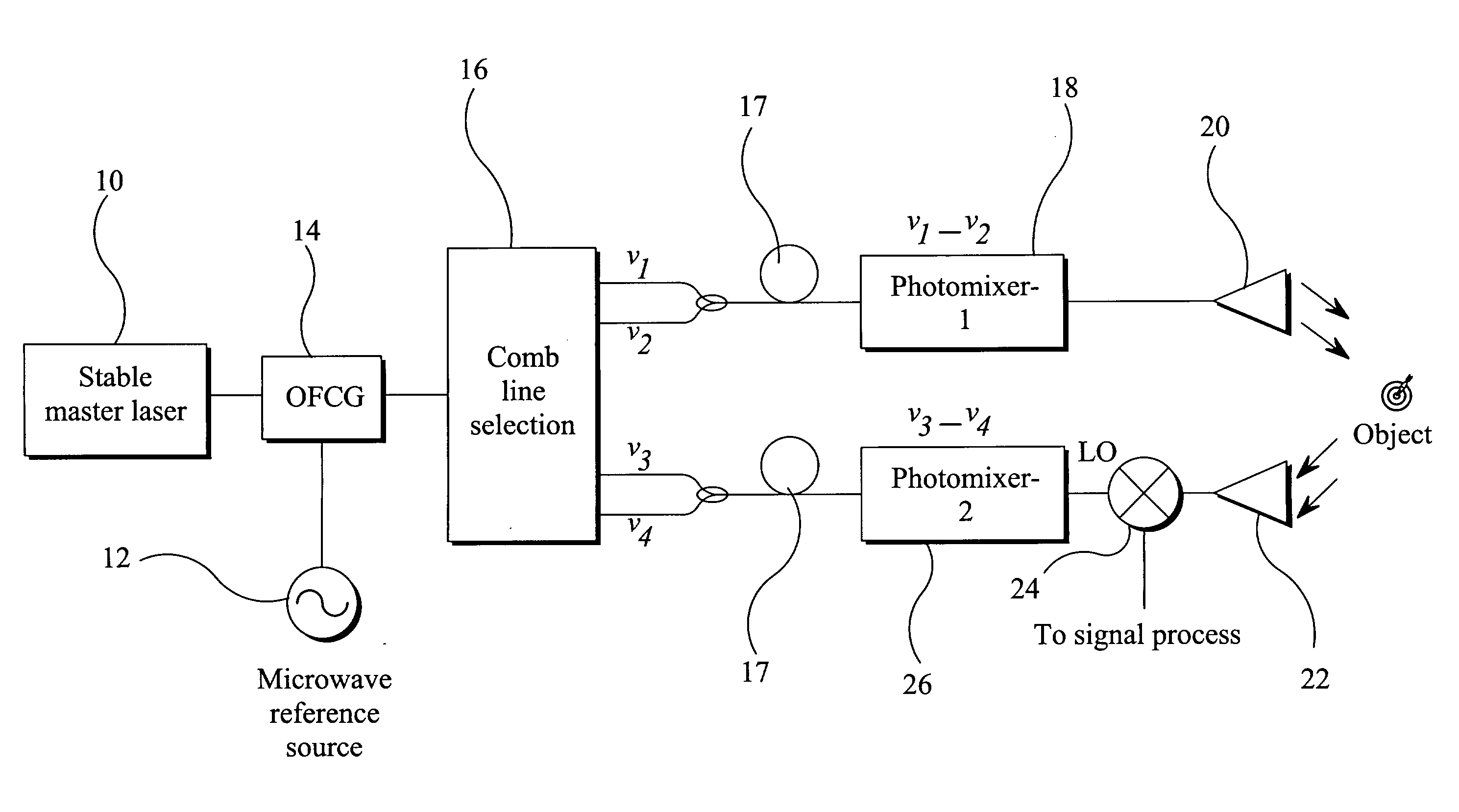
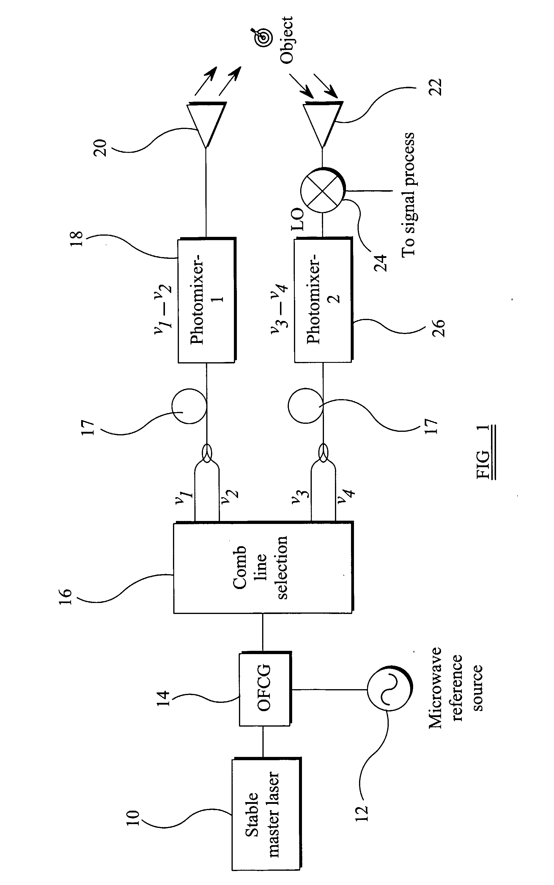
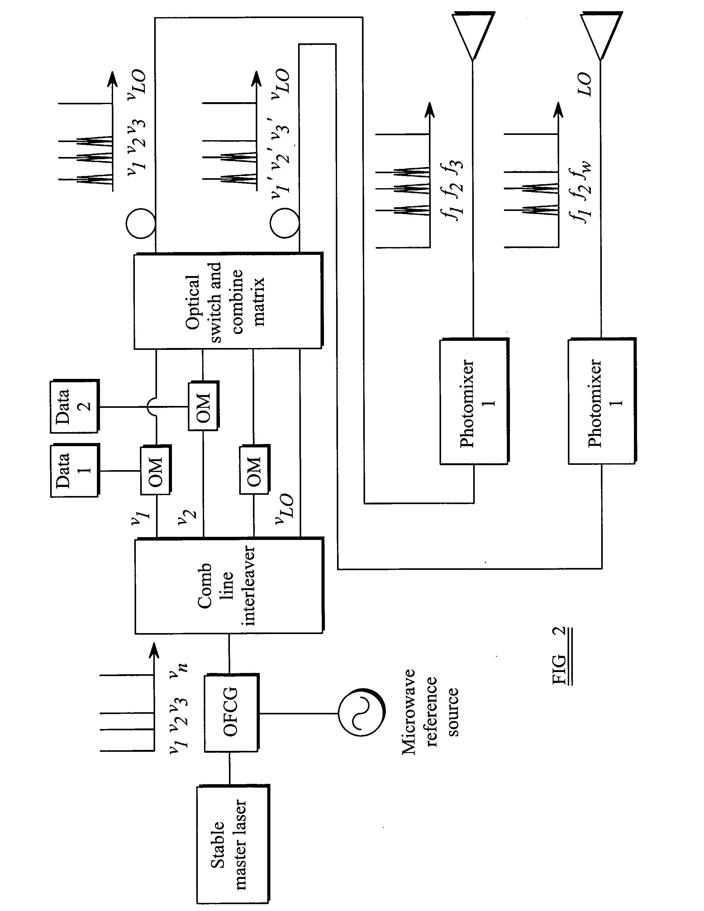
[0039]This invention relates to the generation and reception of electromagnetic signals, in which high frequency signals are generated and detected using a laser and a microwave signal source. The microwave signal source is used to generate multiple signals, separated by the microwave frequency. Selected pairs of these signals are combined to generate the desired high frequency signals, and a local oscillator is also generated and used for frequency down-conversion.

[0040]In this way, the invention provides ultra-low-noise signal generation through optical heterodyning. Optical heterodyning is a method for generating high-frequency signals which is limited (in terms of bandwidth and output power) only by the photodetector used. The high-frequency signal generated is the difference frequency between two laser frequencies, and can be easily varied using tunable (e.g. semiconductor) lasers. However, the laser noise will appear in the output difference frequency signal, and this can be v...


PUM


Abstract

An electromagnetic transmission and reception system comprises a transmitter section and a receiver section. The transmitter section has a first signal source, a second signal source at a lower frequency than the first signal source, and means for generating from the first and second signal sources a plurality of signals with fixed frequency spacing derived from the second signal source frequency. One or more pairs of the plurality of signals are selected, and for the or each pair, the signals of the pair are combined to derive an output signal having a frequency derived from the difference between the frequencies of the signals of the pair. The receiver section combines a received signal, which comprises a received version of the output signal, with a local oscillator signal for frequency down-conversion of the received signal. This local oscillator signal is generated by the transmitter section. This provides a system in which the generation of signals of the desired frequency is achieved by mixing signals of specific frequencies. The reception uses frequency down-conversion using the same signal sources as used for the transmission. This enables a low noise system to be implemented.

Description

BACKGROUND OF THE INVENTION[0001]This invention relates to electromagnetic transmission and reception systems, and relates specifically to the transmission and reception of signals in the Terahertz (THz) radiation band.[0002]Terahertz radiation represents the last band of the radio wave and light spectrum which has not been extensively used for communications systems and other applications. Until recently, bright sources of light and sensors have not been available for this frequency band. The Terahertz band is generally considered to cover the range from 100 GHz (1011 Hz) up to roughly 30 THz (3×10¹³ Hz), and this corresponds to wavelengths from approximately 3 mm to sub-millimeter wavelengths of approximately 0.01 mm. The use of the term Terhertz in this application is intended to cover this range.[0003]The lower frequency limit lies just above the microwave region where satellite dishes and mobile phones operate, whereas the upper limit is located adjacent to infrared frequencies...

Claims


Application Information

Patent Timeline
IPC IPC(8): H04B10/00H04B10/2575
CPCH04B2210/006H04B10/2575
Inventor DAVIES, PHILLIP ANTHONYGOMES, NATHAN JOSEPHSHEN, PENGBO
Owner UNIVERSITY OF KENT
Why Eureka
Try Eureka