
Machine Tool with Two Clamp Points on Separate Carriages

a clamping point and machine tool technology, applied in the field of machine tools, can solve the problems of large production inaccuracies, difficult to achieve good rigidity of the machine, and large manufacturing inaccuracies, and achieve the effect of high manufacturing accuracy and high rigidity

Inactive Publication Date: 2008-09-04
STARRAGHECKERT
View PDF1 Cites 15 Cited by
  • Summary
  • Abstract
  • Description
  • Claims
  • Application Information

AI Technical Summary

Benefits of technology

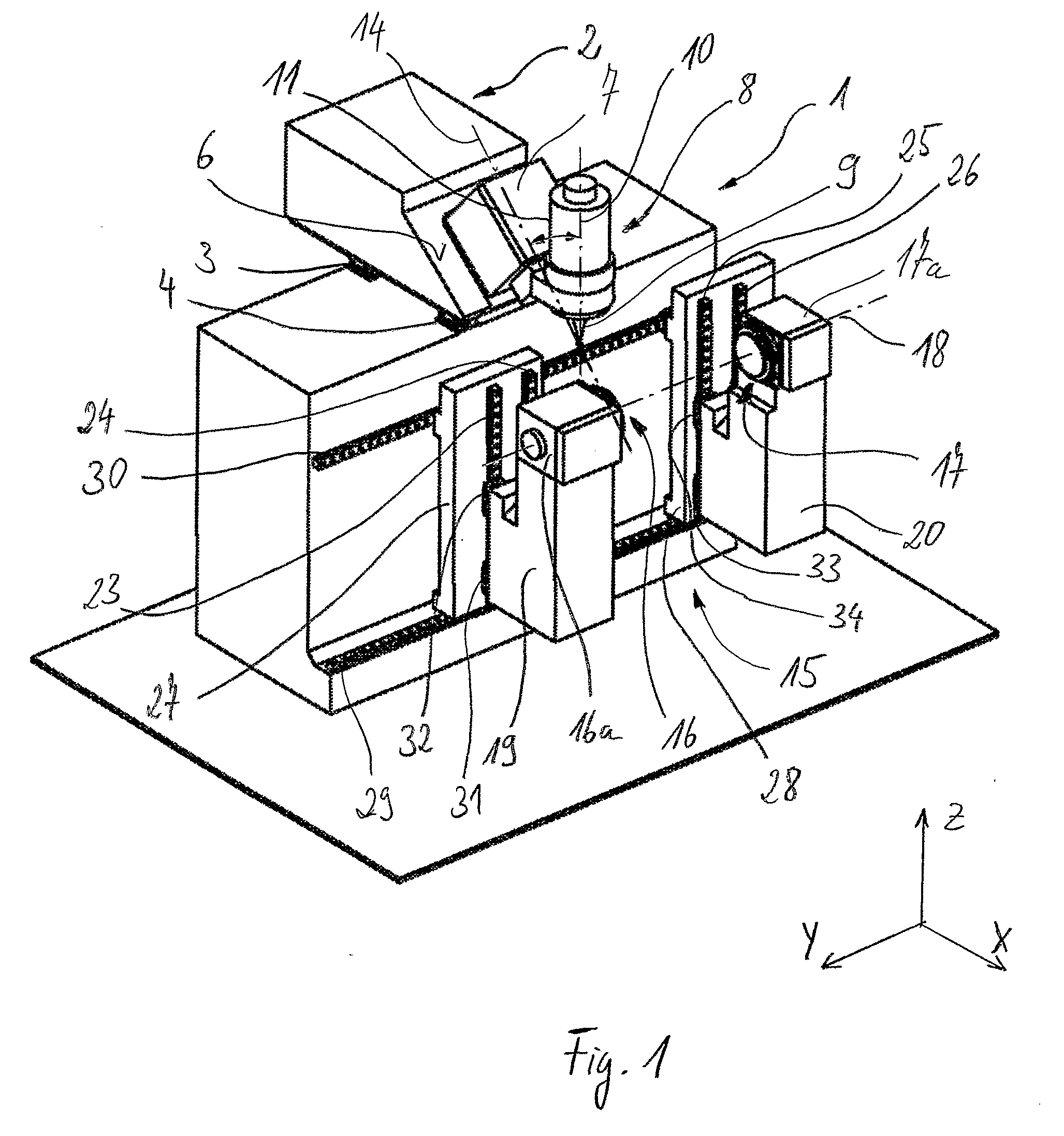
[0007]It is therefore the object of the invention to provide a machine tool of the type specified initially with a workpiece mounting having favourable properties, in particular a more variable workpiece mounting, in which equally good conditions for high manufacturing accuracy are also provided for workpieces of substantially different length. Despite these properties, the machine tools according to the invention should as far as possible also provide conditions such that the machine tool can have a high rigidity with respect to deformations.
[0010]The solution according to the invention can additionally ensure that, as a result of the clamping of the workpiece, the liner movement guides of both clamp points are exposed to substantially the same static loads. Even in the case of the dynamic loads produced during machining, a more uniform distribution can hereby be achieved over the bearing points. In addition, the solution according to the invention has the advantage that from extremely short workpieces to workpieces whose length corresponds to the length of the workpiece axis, all workpiece lengths can be machined under always identical favourable conditions. Finally, the invention also makes it possible to compensate for geometrical inaccuracies of the base frame by means of the controller so that the manufacturing accuracy can be further improved.
[0011]A particularly rigid machine construction which has the advantages of the machine concept according to the invention can be achieved if no more than two linear displacement axes are assigned to the tool holder. In preferred embodiments of the invention, the tool holder can be moved in only two and the workpiece mounting likewise in only two linear machining feed axes. Other than, for example, in WO 03 / 064089 A1, despite the at least four linear displacement axes, both the tool holder and also the workpiece mounting have the smallest possible number of linear displacement axes which results in a high manufacturing accuracy of the machine tools according to the invention.
[0012]At least the movements of the two clamp points along one displacement feed axis, preferably in both displacement feed axes, should be synchronised with one another. Such synchronisation can preferably be achieved by means of hardware- or software-based regulation as part of the controller. The mechanically separate displaceability of the two clamp points or carriages along the same axis can be achieved with particularly low design expenditure if both carriages are arranged on the same rails of the linear movement guides provided for this purpose. In order to achieve a secure and stable arrangement of a workpiece between the two clamp points of the workpiece mounting, detectors can be provided for determining instantaneous positions of both clamp points for the synchronous movement of the two clamp points. Their signals should be fed to a controller. On the basis of the detection signals, the controller can compensate between the setpoint and actual points of the two carriages or the speed of the two synchronously moving carriages. For this purpose the controller can also contain one or more control loops.
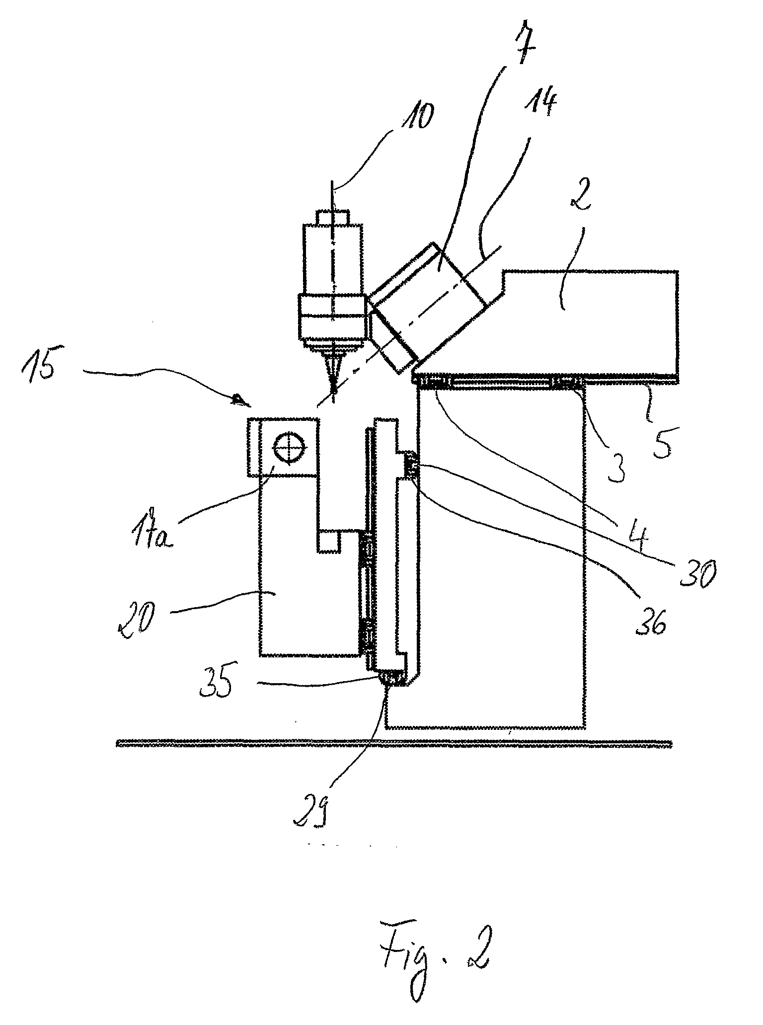
[0013]The invention is of particular importance in connection with machine tools whose tool holder is pivotable about a pivot axis, where the pivot axis preferably encloses an acute angle with the tool axis of the clamped tool. Furthermore, in appropriate further developments the pivot axis and the tool axis intersect, or at least run very close past one another, where the point of intersection of the position having the shortest distance should be located in the area of the tool tip. With such a solution, pivoting movements of the tool holder in which the tool tip retains its position despite the pivoting movement can be made along one or more translational axes without complex compensating movements. In addition, the torque loading of the axis of rotation as a result of clamping forces is minimized in this case. Such pivoting movements can thus be used for alignment or tracking of the tool whereby good surface quality and accuracy can be achieved, even when the workpiece to be manufactured has a complex contour.
[0014]A machine tool according to the invention can furthermore have a circular station whose two clamp points can receive the workpiece and during machining of the workpiece, the latter can be set in rotational movement which is provided as a machining feed movement or as a component of the feed movement of the workpiece relative to the milling tool. The circular station can preferably execute endless rotational movements. In connection with such machine tools as are already described in EP 0 659 520 B1, a number of additional advantages are obtained in connection with the separate and multi-axial displaceability of the preferably two clamp points according to the invention. These consist, for example, in a possible reduction in the moving masses, in particular because the circular station can be more slender. The short machining times which are possible with this machine concept anyway can be further shortened as a result of the small masses to be moved despite the high machining accuracy. The chip flow and the accessibility for exchanging a workpiece or front machining of the workpiece is also improved by using the invention in such a machine tool concept. The content of EP 0 659 520 B1 is therefore completely included by reference particularly with regard to the fundamental structure and the operating mode of such machine tools.

Problems solved by technology

Particularly in the case of elongated workpieces such as turbine blades or vanes, for example, these are frequently clamped between two clamp points to avoid bending and the resulting large production inaccuracies.
However, this has the disadvantage that particularly with shorter workpieces on the carriage, the bearings of the carriage are subject to a strongly unilateral loading which can result in manufacturing inaccuracies.
This conceptual design of the machine tool makes it difficult to achieve good rigidity of the machine.
In addition, the accessibility of the workpiece is restricted in the X direction despite the movability of the two carriages of each workpiece mounting.
Particularly the fact that a second workpiece mounting is provided can be detrimental to the accessibility of the workpiece during its machining.

Method used


Image

  • Machine Tool with Two Clamp Points on Separate Carriages
  • Machine Tool with Two Clamp Points on Separate Carriages
  • Machine Tool with Two Clamp Points on Separate Carriages

Examples


Embodiment Construction

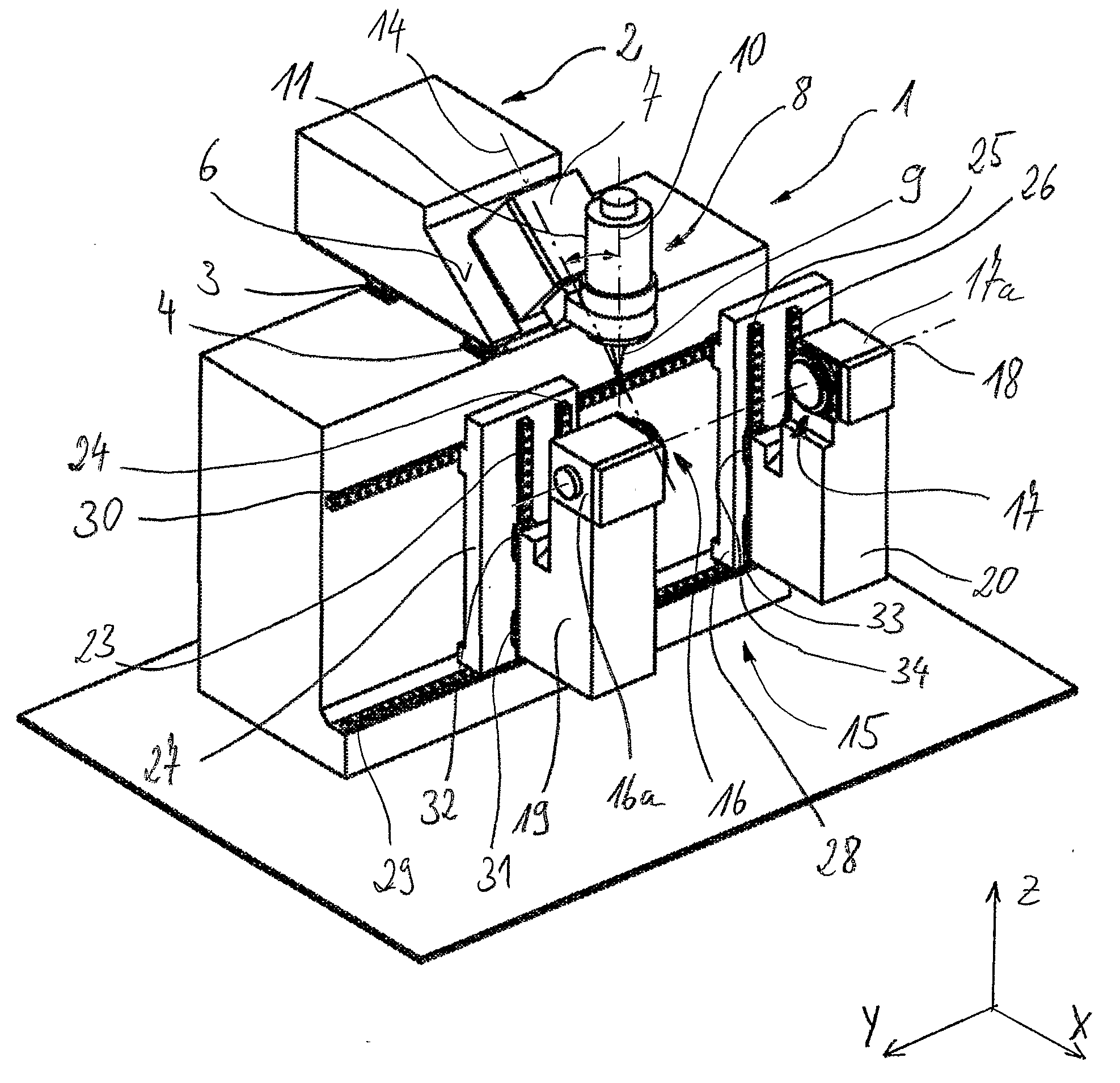
[0019]Referring to the drawings in particular, The machine tool shown highly schematically in FIG. 1 is provided with a machine frame 1 having a first carriage 2 arranged on its upper side. The carriage 2 can be driven in the X direction of a Cartesian coordinate system. The displaceability of the carriage 2 is achieved by two linear movement guides running parallel to one another in which a plurality of carriage rollers 3, 4 are arranged on linear displacement rails 5. Of these only one of the rails 5 can be seen in the figures. Such linear movement guides in which rolling bodies circulate in circulating channels in the carriage roller 3, 4 are previously known in many cases. In the present case, the carriage rollers 3, 4 are secured in a fixed position on the machine frame 1 whilst the rails 5 are attached to the movable carriage 2.

[0020]The carriage 2 is provided with a sloping surface on which a tool carriage 7 is located. The tool carriage 7 can be driven in the X and Z directi...


PUM

PropertyMeasurementUnit
rotational movementaaaaaaaaaa
displacementaaaaaaaaaa
linear displacementaaaaaaaaaa

Abstract

The invention relates to a machine tool for milling workpieces, provided with at least two linear displacement axes and at least one pivot axis for carrying out relative movements between a tool and the corresponding workpiece with a workpiece mounting in which a workpiece may be clamped between two clamping points, whereby one of the linear displacement axes is provided as workpiece axis of the workpiece mounting, by means of which the workpiece may be linearly driven, which is furthermore provided with a tool holder for mounting a cutting machining tool, driven in rotation about a tool axis by means of a tool drive. The same conditions are achieved for workpieces of greatly different length for a highly accurate production, whereby two physically separate carriages (27, 28) for the workpiece mounting are provided, on each of which one of the clamping points (16, 17) is arranged and which both may be linearly driven along the same workpiece axis independently of each other.

Description

CROSS REFERENCE TO RELATED APPLICATIONS[0001]This application is a United States National Phase application of International Application PCT / CH2006 / 000257 and claims the benefit of priority under 35 U.S.C. § 119 of CH 856 / 05 filed May 16, 2005, the entire contents of which are incorporated herein by reference.FIELD OF THE INVENTION[0002]The present invention pertains to a machine tool for milling workpieces, which is provided with a tool holder for mounting a cutting machine tool which is rotationally driven for this purpose, which has a workpiece mounting in which a workpiece may be clamped between two clamp points, wherein the machine tool has a plurality of driven displacement axes, the displacement axes being provided, individually or in combination with one another, for generating machining feed movements as relative movement of the machining tool relative to the workpiece during machining of the tool on the workpiece, wherein the tool holder is provided with at least one linea...

Claims


Application Information

Patent Timeline
Patent Type & Authority Applications(United States)
IPC IPC(8): B23C7/00B23Q35/10
CPCB23C1/06B23C3/18B23C2215/44B23Q1/54Y10T409/305656Y10T409/307672Y10T29/5114Y10T409/303808B23Q1/623B23B23/00B23Q1/62B23Q39/02
Inventor BETSCHON, LUKASGLAUS, CHRISTIAN
Owner STARRAGHECKERT
Learn More