
Solid polyelectrolyte type fuel cell and method of producing the same

a fuel cell and polyelectrolyte technology, applied in the direction of cell components, sustainable manufacturing/processing, paper/cardboard containers, etc., can solve the problems of low catalyst activity for electrochemical reaction at the electrode, low catalyst use efficiency of catalyst carried on carbon particles, and reducing reliability, etc., to achieve excellent reliability, reduce electric interface resistance, and improve contact area and cohesion

Inactive Publication Date: 2008-09-04
SHARP KK
View PDF6 Cites 16 Cited by
  • Summary
  • Abstract
  • Description
  • Claims
  • Application Information

AI Technical Summary

Benefits of technology

[0021]It is an object of the present invention to solve the above problems, and to provide a solid polyelectrolyte type fuel cell having excellent reliability and a method of producing the same, by reducing electric interface resistance between an electrode and a solid polyelectrolyte membrane by improving contact area and cohesion between the electrode and the solid polyelectrolyte membrane.
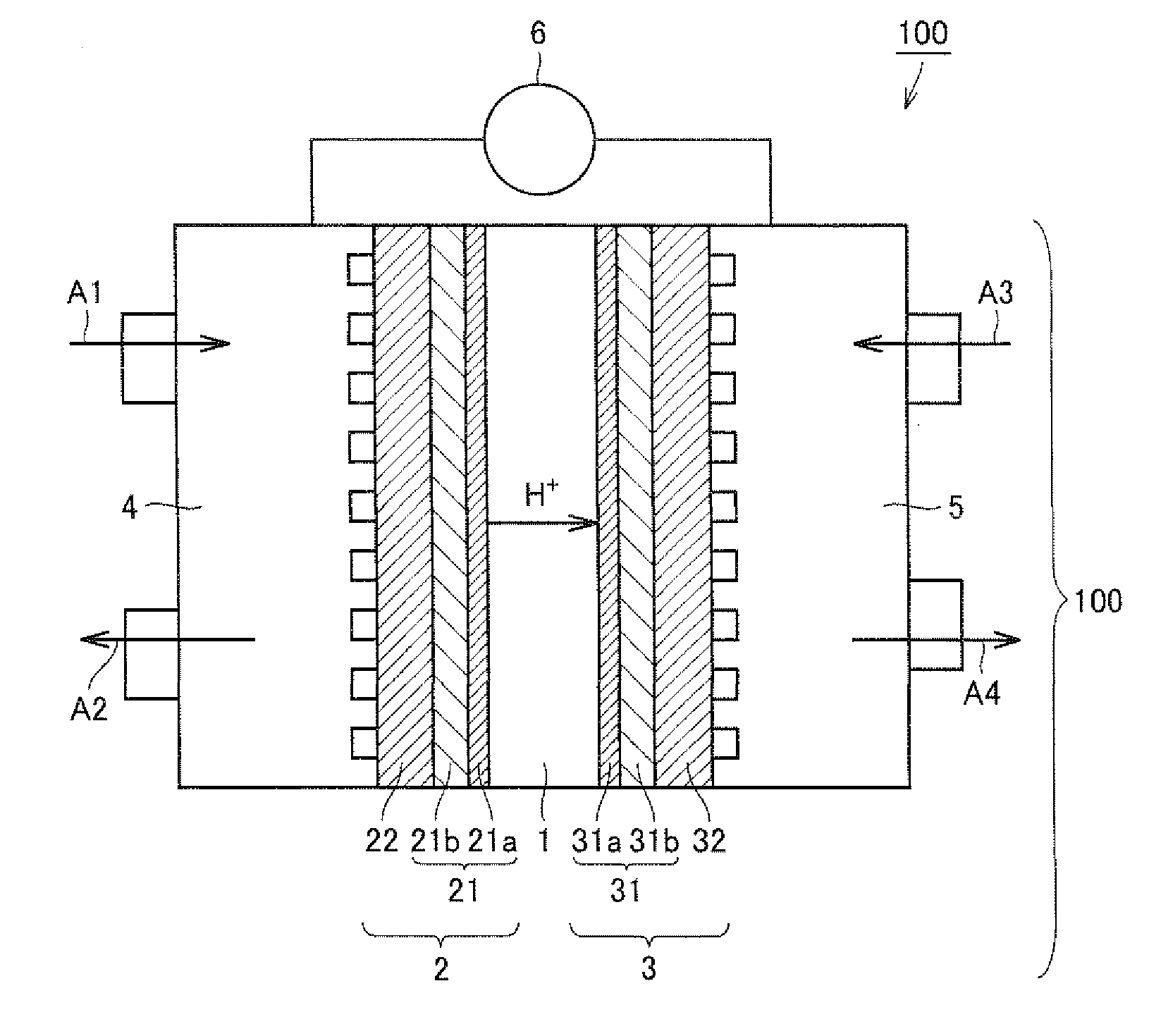
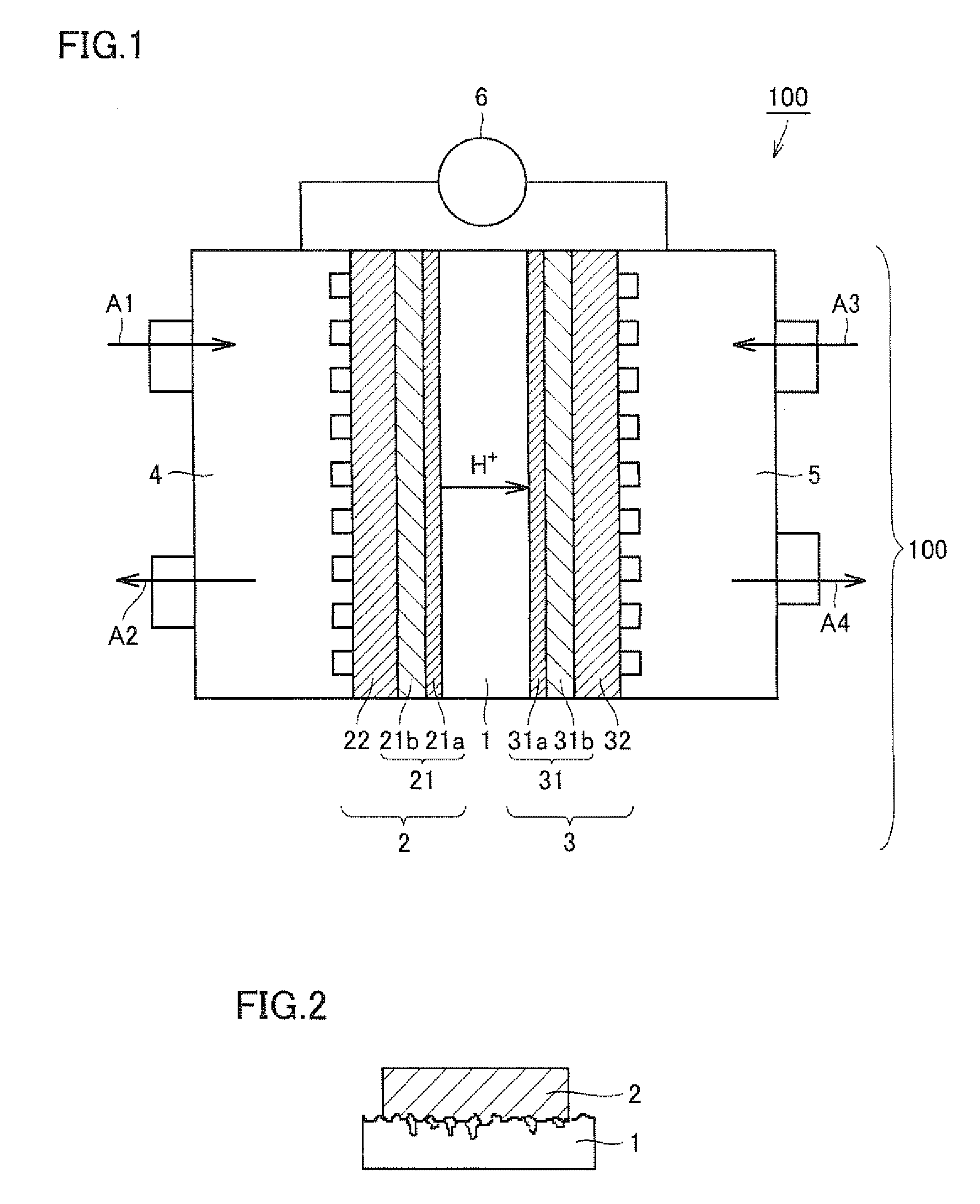
[0032]According to the present invention, by making at least one surface of the polyelectrolyte membrane as the bumpy face, and forming a catalyst layer so as to be close contact with the bumpy shape, it is possible to increase the contact area between the catalyst layer and the polyelectrolyte membrane, and to improve cohesion between the catalyst layer and the polyelectrolyte membrane. Accordingly, the interface resistance between the catalyst layer and the polyelectrolyte membrane is reduced, and a fuel cell of high reliability can be obtained.

Problems solved by technology

When the cohesion between the electrode and the polyelectrolyte membrane is poor, there arises a problem of reduction in reliability.
In such conventional production methods, the use efficiency of catalyst carried on carbon particles is low in the aforementioned three-phase interface, and a large quantity of catalyst fails to function effectively in electrochemical reaction, so that catalyst activity for electrochemical reaction at the electrodes is low.
This is attributable to the fact that the polyelectrolyte is unable to penetrate inside micropores of carbon particles which are carriers because the polyelectrolyte solution has certain viscosity, and particle sizes of ionomer of polyelectrolyte dispersed in the solution are large, and it is impossible to make the polyelectrolyte into contact with the catalyst metal carried inside the micropores.
In such a case, however, due to the complexity of the shape of the bumpy face, the contact area between the electrode that is connected to the solid polyelectrolyte membrane by e.g., thermocompression bonding, and the solid polyelectrolyte membrane is small, so that it is difficult to sufficiently make use of advantage of providing a bumpy face on the surface of the solid polyelectrolyte membrane.
When an adhesive layer made of polymer is provided between the electrode and the solid polyelectrolyte, the problem of large electric resistance arises in association with the increased thickness of the electrolyte membrane.

Method used


Image

  • Solid polyelectrolyte type fuel cell and method of producing the same
  • Solid polyelectrolyte type fuel cell and method of producing the same
  • Solid polyelectrolyte type fuel cell and method of producing the same

Examples


example 1

Fabrication of Polymer Solid Electrolyte Membrane Having a Surface Formed with Bumpy Face

[0095]As a polyelectrolyte membrane, Nafion (registered trademark) 117 (available from Du Pont) was used. The polyelectrolyte membrane was sandwiched by two dies having a bumpy shape of surface roughness (Ra) of about 30 μm, and pressed at 100° C. under 5 MPa for 3 minutes. As a result, the bumpy shapes of the dies were transferred on both sides of the polyelectrolyte membrane, and a bumpy face having surface roughness of about 10 μm was formed on the surface of the polyelectrolyte membrane.

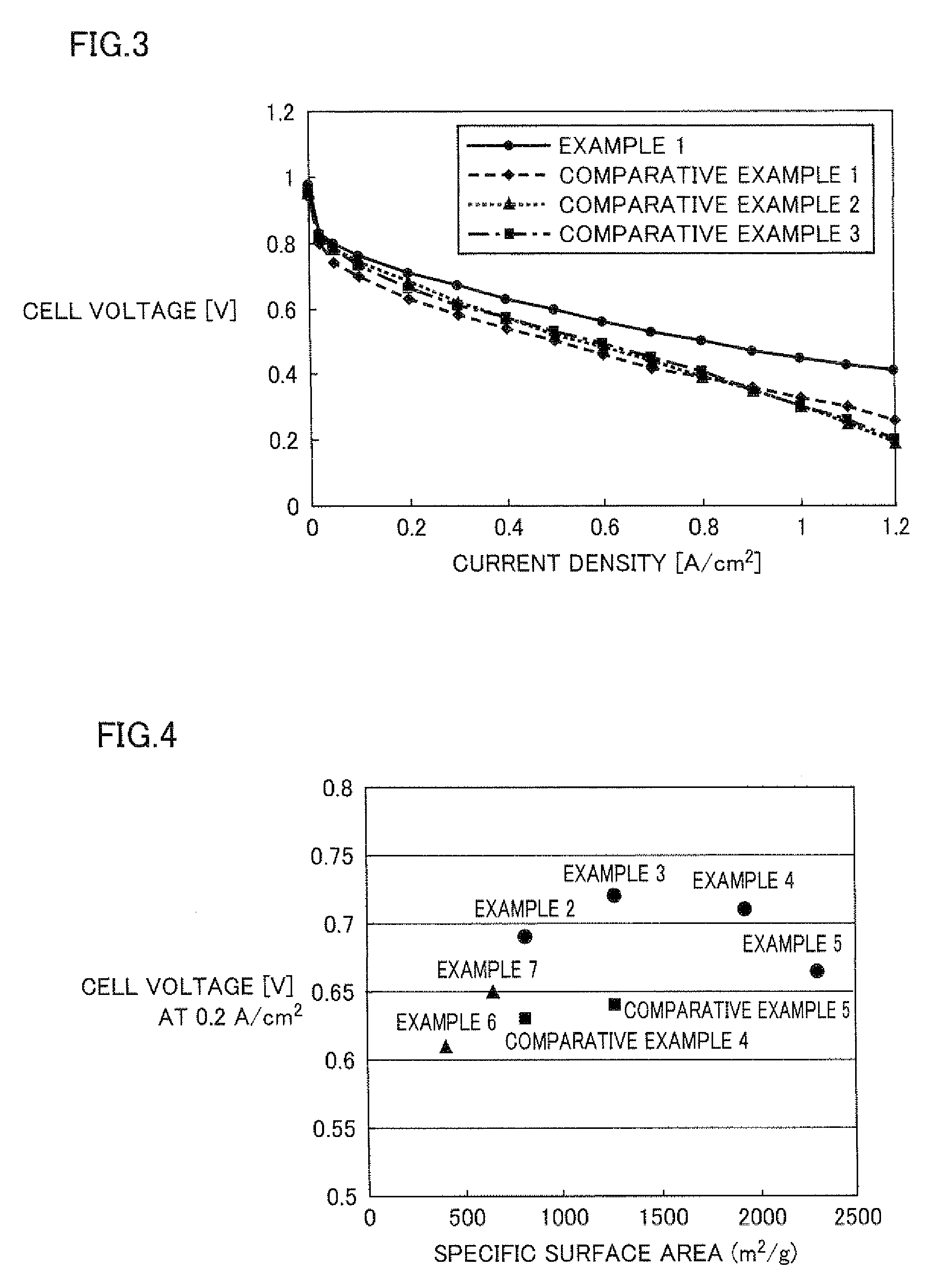
[0096]Carbon black (acetylene black) having a specific surface area of 1120 m / g was suspended in a solution of 2 (4-chlorosulfonylphenyl)ethyltrichlorosilane in dichloromethane, and stirred for 2 hours at room temperature. Next, the suspension was filtered and dried under reduced pressure. In this manner, carbon particles having surfaces modified with a proton dissociative functional group were obtained.

[0097...

examples 2 to 5

[0109]Solid polyelectrolyte type fuel cells were produced in a similar manner as described in Example 1 except that carbon blacks having a specific surface area of 810 m2 / g (Example 2), 1270 m2 / g (Example 3), 1925 m2 / g (Example 4), and 2300 m2 / g (Example 5), respectively were used as carbon black.

examples 6 and 7

[0110]Solid polyelectrolyte type fuel cells were produced in a similar manner as described in Example 1 except that carbon blacks having a specific surface area of 396 m2 / g (Example 6), and 643 m2 / g (Example 7), respectively were used as carbon black.


PUM

PropertyMeasurementUnit
specific surface areaaaaaaaaaaa
roughnessaaaaaaaaaa
shapeaaaaaaaaaa

Abstract

To provide a solid polyelectrolyte type fuel cell having excellent reliability and a method of producing the same by reducing electric interface resistance between an electrode and a solid polyelectrolyte membrane by improving contact area and cohesion between the electrode and the solid polyelectrolyte membrane. The present invention relates to a solid polyelectrolyte type fuel cell including a polyelectrolyte membrane and a pair of electrodes sandwiching the polyelectrolyte membrane, and the electrodes have a catalyst layer containing catalyst-carrying carbon particles, and at least one surface of the polyelectrolyte membrane has a bumpy face in which a bumpy shape is formed, and the catalyst layer is formed in close contact with the bumpy shape of the bumpy face.

Description

[0001]This nonprovisional application is based on Japanese Patent Application No, 2006-347490 filed with the Japan Patent Office on Dec. 25, 2006, the entire contents of which are hereby incorporated by reference.BACKGROUND OF THE INVENTION[0002]1. Field of the Invention[0003]The present invention relates to a solid polyelectrolyte type fuel cell having excellent reliability and a method of producing the same.[0004]2. Description of the Background Art[0005]Various kinds of fuel cells are known such as one of a phosphate type, and in recent years, development of solid polymer type fuel cells using a solid electrolyte membrane as an electrolyte, in particular, is actively made. A solid polyelectrolyte type fuel cell includes a proton-conductive solid polyelectrolyte formed of, e.g., a perfluorosulfonate membrane, and a pair of electrodes, namely, an anode and a cathode which are opposite to each other via the solid polyelectrolyte. The anode is supplied with fuel such as pure hydrogen...

Claims


Application Information

Patent Timeline
Patent Type & Authority Applications(United States)
IPC IPC(8): H01M8/10B05D5/12B29C65/02
CPCH01M4/881H01M4/8828H01M4/8882H01M4/90H01M4/92Y10T156/10H01M4/926H01M8/1006H01M2008/1095Y02E60/521H01M4/921Y02E60/50Y02P70/50
Inventor SHINDOH, TAISUKETAKATERA, TSUTOMU
Owner SHARP KK
Learn More