Microneedle sheet and method for manufacturing the same

a technology of microneedle and manufacturing method, which is applied in the field of microneedle sheets, can solve the problems of poor productivity, high cost, and difficulty in obtaining satisfactory medicinal benefits, and achieve the effects of low manufacturing cost, high yield and smooth skin insertion

Inactive Publication Date: 2008-09-11
FUJIFILM CORP
View PDF5 Cites 38 Cited by
  • Summary
  • Abstract
  • Description
  • Claims
  • Application Information

AI Technical Summary

Benefits of technology

[0036]According to the fourteenth aspect of the present invention, since a backing sheet is adhered to the stamper via the polymer resin, and the polymer resin is peeled off from the stamper, a durable microneedle sheet can be manufactured at high yield.
[0037]According to the aspects of the present invention as have been described, a microneedle sheet having the array of microneedles that can be smoothly inserted into the skin without damaging the shapes of the formed microneedles, and can be manufactured at low manufacturing costs and high yield; and a method for manufacturing such a microneedle sheet can be provided.

Problems solved by technology

However, since the region to adhere these substances has been limited to the surface of the skin, the adhered medicals or the like have been removed due to sweating or the contact of foreign matters at times, and the administration of an adequate quantity has been difficult.
In order to medicate medicals deep into the skin, since it has been difficult to accurately control the depth of penetration by the method using the osmosis by the diffusion of such medicals, it has been difficult to obtain satisfactory medicinal benefits.
However, in the invention disclosed in National Publication of International Patent Application No. 2002-517300, since a substrate surface composed of Si, metals or the like is directly subjected to etching process when a functional micro pile is manufactured, there has been a problem of poor productivity and high costs.
Since the inventions disclosed in Japanese Patent Application Laid-Open No. 2003-238347 and Japanese Patent Application Laid-Open No. 2006-51361 are methods for fabricating what is to be a functional micro pile by the injection molding of a resin material, it has been difficult to release a functional micro pile having a high aspect ratio from the mold, and to obtain a perfect product because defects arc easily produced in the edge portions, and there has been a problem of low yield in manufacture.
Also since the functional micro pile and the like manufactured by the methods described in National Publication of International Patent Application No. 2002-517300, Japanese Patent Application Laid-Open No. 2003-238347 and Japanese Patent Application Laid-Open No. 2006-51361 are manufactured not considering easy insertion into the skin, there has been a problem of difficulty in smooth insertion into the skin.

Method used


Image

  • Microneedle sheet and method for manufacturing the same
  • Microneedle sheet and method for manufacturing the same
  • Microneedle sheet and method for manufacturing the same

Examples


example 1

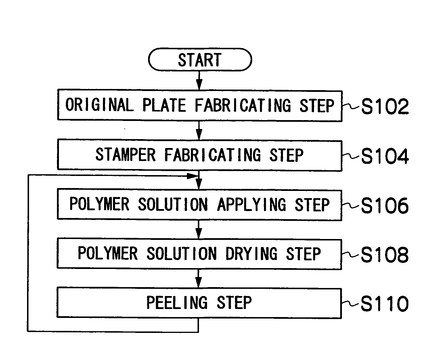
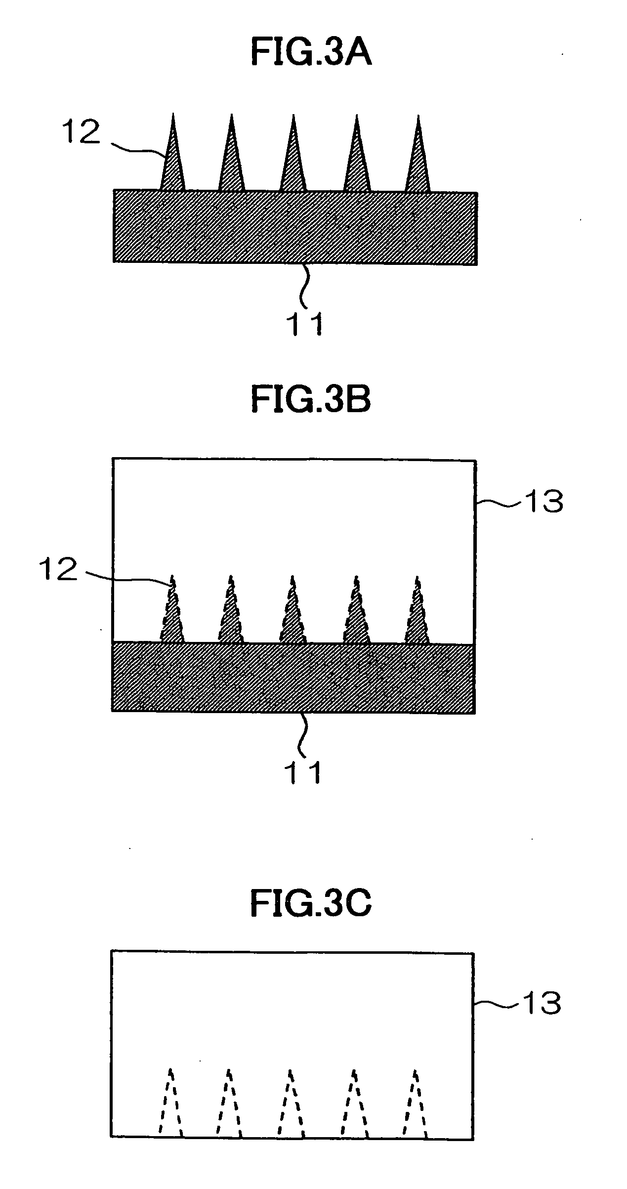
[0076]In example 1, a metal plate composed of Ni was cut using a diamond tool to fabricate an original plate 11 wherein an array of four-sided pyramids each having a base X of a pyramidal portion 12 shown in FIG. 5B of 200 μm, a height Y of 400 μm, and a pitch of 1000 μm.

[0077]A silicone resin (PDMS) was poured into the original plate 11 and cured to fabricate a stamper 13 of an inverted shape of the original plate 11 shown in FIG. 3C.

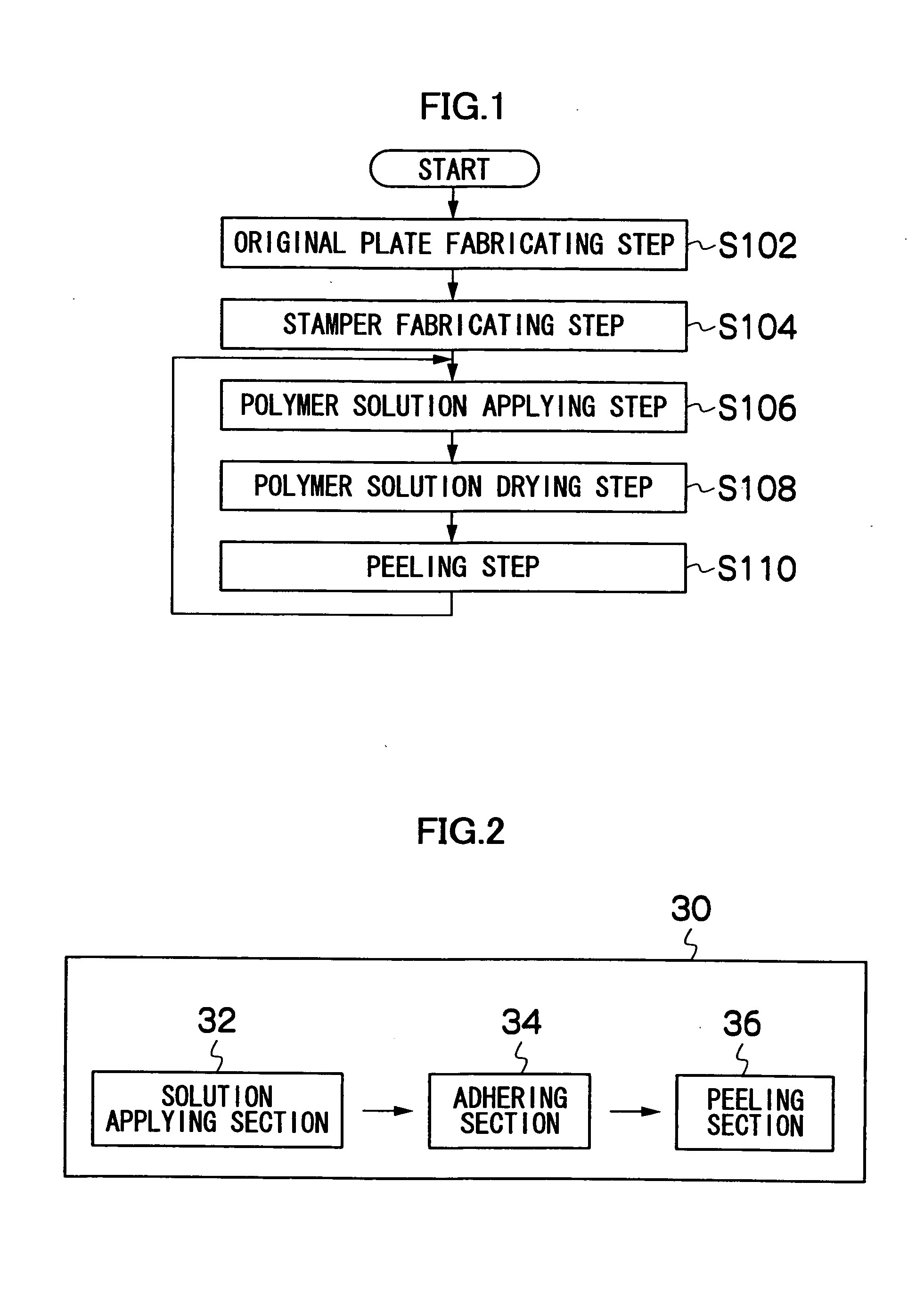
[0078]After gelatin was dissolved in water, stirred and swollen, the solution was heated to 40° C. and dissolved to prepare a solution wherein a polymer resin of a gelatin concentration of 20% was dissolved. The solution was applied onto the concave-convex surface of the stamper 13 using a spin coater. An appropriate quantity of medicals to be administered is mixed in the solution.

[0079]After blasting cool air of a temperature of 15° C. to the coating of the solution wherein the polymer resin was dissolved prepared by dissolving gelatin in water for 20...

example 2

[0081]The concentration of gelatin and drying conditions in example 1 were changed to change the shrinkage factor of gelatin when solidified, and a microneedle sheet 16 was fabricated. Samples having shrinkage factors from 50% to 75% measured from observation through a microscope were prepared. A constant load per needle was given to these samples to check whether the needles can be inserted into a simulated skin (silicone rubber) or not. The results are shown in Table 1. As Table 1 shows, it was confirmed that as the shrinkage was larger, the side planes (ridge lines) of a pyramid were more curved inward, and the needles could be more easily inserted at a low load.

TABLE 1Shrinkage factorLoad required for insertion75%Inserted at 10 g / needle or more70%Inserted at 10 g / needle or more60%Inserted at 30 g / needle or more50%Inserted at 40 g / needle or more


PUM


Abstract

In a microneedle sheet having a microneedle array composed of a large number of microneedles Formed on the surface of the sheet, the ridge lines or conical plains of the microneedles are curved inward into said microneedles. Since the ridge lines or conical planes of the microneedles have a shape curved inward into the microneedles, a microneedle sheet that can be smoothly inserted into the skin can be provided.

Description

BACKGROUND OF THE INVENTION[0001]1. Field of the Invention[0002]The present invention relates to a microneedle sheet and a method for manufacturing and thereof; and specifically to a microneedle sheet that can easily, safely and efficiently inject medicals or the like into a surface or horny layer of a skin, and a method for manufacturing such a microneedle sheet.[0003]2. Description of the Related Art[0004]Heretofore, a majority of methods to administer medicals or the like through the surface of a living body, such as the skin and mucous membrane, has been a method to adhere mainly a liquid or powdered substance. However, since the region to adhere these substances has been limited to the surface of the skin, the adhered medicals or the like have been removed due to sweating or the contact of foreign matters at times, and the administration of an adequate quantity has been difficult. In order to medicate medicals deep into the skin, since it has been difficult to accurately contro...

Claims


Application Information

Patent Timeline
Patent Type & Authority Applications(United States)
IPC IPC(8): A61M5/32
CPCA61M37/0015A61M2037/0053A61M2037/0046
Inventor OGAWA, SHOTARO
Owner FUJIFILM CORP
Why Eureka
Try Eureka