Ultrasonic Imaging Device

a technology of ultrasonic imaging and imaging device, which is applied in the field of ultrasonic imaging technique, can solve the problems of increasing the pulse width of the second-order harmonic echo signal obtained as an output signal, unavoidable use of filters having sharp band-cutoff characteristics or narrow band-pass characteristics, and a particular serious problem

Active Publication Date: 2008-09-18
FUJIFILM HEALTHCARE CORP
View PDF7 Cites 9 Cited by
  • Summary
  • Abstract
  • Description
  • Claims
  • Application Information

AI Technical Summary

Benefits of technology

[0065]FIG. 13 shows examples of adder output signal waveforms for the echo signals obtained from the internal point-reflector of the vital soft tissue in the three-pulse method of the present invention when respective transmitted pulses contain phase errors.
[0066]The output signals of the adder 13, that is, input signals of the band-pass filter A14, that are obtained when the second transmitted pulse wave is shifted through 20° in phase, and filter output signals obtained similarly to FIG. 4 when band-pass central frequencies are set to frequencies of the fundamental wave and second-order harmonics are shown by way of example in FIGS. 13A, 13B, 13C. A signal obtained in the example of FIG. 5, that is, a signal obtainable without a phase error in the pulse inversion method is shown in FIG. 13A for comparison. FIG. 13C shows an example where the sum signal of three transmitted pulse waves is adjusted to zero by shifting a phase of the third transmitted pulse wave by 10° for the 20° phase shift of the second transmitted pulse wave.
[0067]The envelope signal of a transmitted pulse wave is represented by A(t) as a function of time “t”. When first, second, and third transmitted pulse signals P1(t), P2(t), P3(t) in the embodiment of the present invention contain no phase errors, these signals can be represented as follows using numeric expressions (1), (2), (3). At this time, the relationship shown in numeric expression (4) is established:
[0068]In this case, if the third pulse is adjusted to be representable as shown in numeric expression (6) or (7), numeric expression (4) can be established, regardless of the phase error φ. FIG. 13C shows a result of such correction of the third pulse and indicates that despite the phase error in the second pulse, the fundamental wave components in the output signal of the adder 13 are canceled. Therefore, the fundamental wave components in the signal obtained by summing up an N number of receive echo signals are canceled since numeric expression (4) is established and since the sum signal of the N number of pulse waveforms used for transmission is generally zero in substance.
[0069]In FIG. 14, a peak-to-peak value of the amplitude of an output signal from the adder 13 (i.e., output signal relative amplitude PP value) is shown as a function of a phase error given in degrees to a second pulse. The vertical axis shown in FIG. 14 denotes the PP value, and the horizontal axis denotes the phase error. Section (a) in FIG. 14 is associated with a non-corrected third pulse for the signal amplitude standardized using a value with which the pulse inversion method was executable without a phase error, and section (b) is associated with a corrected third pulse. If the phase error reaches 20°, even when the third pulse is corrected, signal amplitude derived from nonlinear propagation through the soft tissue and not derived from the contrast-imaging microbubbles decreases to at least half the signal amplitude obtained in the conventional pulse inversion method. Such a significant decrease in signal amplitude will prevent the present invention from fully developing the advantageous effects thereof. Hence, to fully obtain the advantageous effects of the invention, it is desirable that the phase error of the transmitted pulse be 10° or less.
[0070]As described above, it is possible, by carrying out the present invention, to extract echo signals derived only from contrast-imaging microbubbles, not including any internal signal components of a soft tissue which are derived from nonlinear propagation or the like.

Problems solved by technology

This technique, however, has an unsolved problem in that using only a band-pass filter to extract these second-order harmonic components from an echo signal increases the pulse width of the second-order harmonic echo signal obtained as an output signal.
This problem stems from the fact that since the amplitude of the fundamental wave component included in the echo signal is at least one digit greater than the amplitude of the second-order harmonic components, it is unavoidable to use the filter having sharp band-cutoff characteristics or narrow band-pass characteristics.
This problem has been particularly serious because two-dimensional image display of the bloodstream deteriorates the image itself in distance resolution.

Method used


Image

  • Ultrasonic Imaging Device
  • Ultrasonic Imaging Device
  • Ultrasonic Imaging Device

Examples


Embodiment Construction

[0036]An embodiment of the present invention will be described hereunder with reference being made to the accompanying drawings. In FIGS. 4, 5, 6, 7, 8, 9, 10, 11, 12, 13, 15, 16, a vertical axis denotes signal amplitude (shown in relative value) proportional to a sound pressure, and a horizontal axis denotes time (μs).

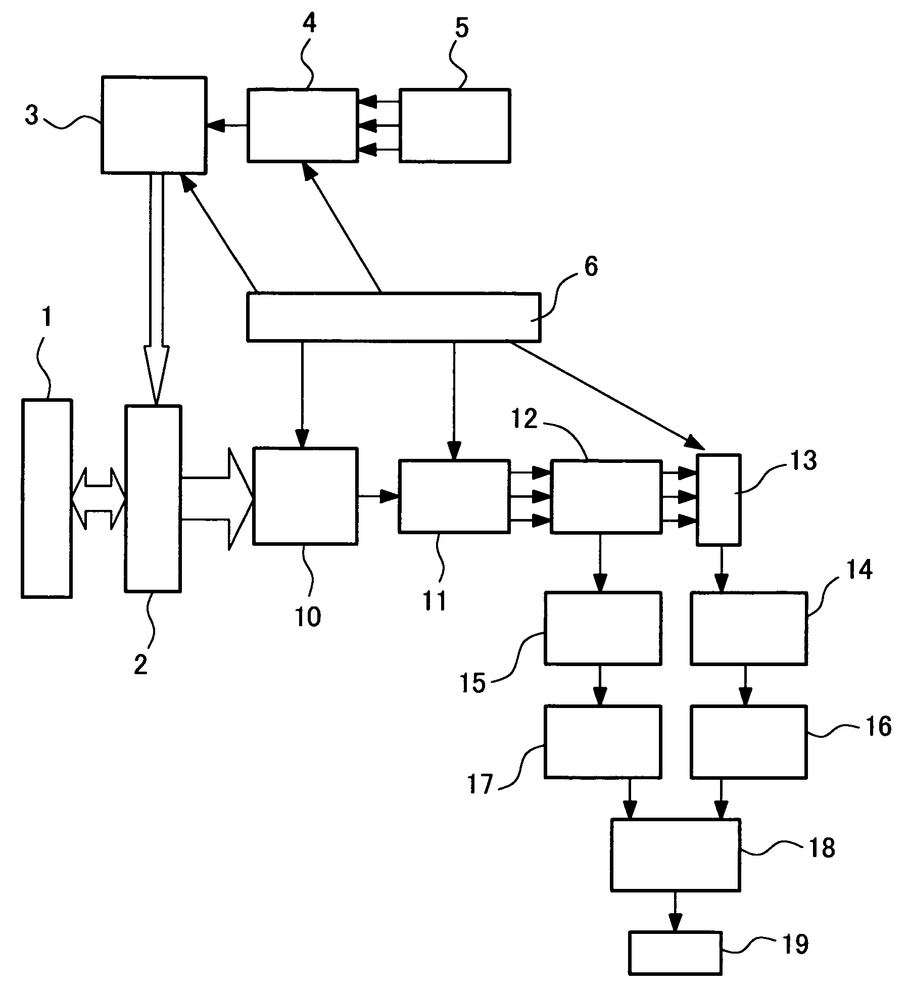
[0037]FIG. 3 is a typical example of a block diagram showing an ultrasonic imaging system constructed to embody the present invention.

[0038]Elements that constitute an ultrasonic probe 1 are each connected to a transmit beamformer 3 and a receive beamformer 10 via transmit / receive selection switches 2. The transmit beamformer 3 generates signals that become ultrasonic pulses with directivity when transmitted through the elements. Each signal is generated using a waveform that has been selected and read out from a transmit waveform memory 5 by a transmit waveform selector 4 under control of a transmit / receive sequence controller 6. The signal is converted into the ultr...


PUM


Abstract

This invention provides an ultrasonic imaging system that implements imaging by distinguishing sharply and definitely the echo components generated by scattering in a microbubble contrast medium, from the tissue harmonic components generated by nonlinear propagation of a transmitted pulse. This ultrasonic imaging system, constructed to transmit/receive ultrasonic pulses to/from a living body and form a contrast image of the inside of the living body by using the contrast-imaging microbubbles, repeats the transmitting/receiving operations four times in all, under the same transmitting/receiving focus conditions at different phase angles [(a)=0°, (b)=120°, (c)=−120°, (d)=180°] of the carrier of a transmitted pulse wave including a common envelope signal, sums up three time-series receive echo signals associated with (a), (b), (c), forms the contrast image, sums up two time-series receive echo signals associated with (a), (d), forms an image of the living body having a nonlinear pulse propagation property, and makes a superimposed display of the two kinds of images.

Description

FIELD OF THE INVENTION[0001]The present invention relates generally to ultrasonic techniques for imaging the inside of a living body by transmitting / receiving ultrasonic waves to / from the living body. More particularly, the invention relates to an ultrasonic imaging technique for acquiring images using a microbubble contrast medium.BACKGROUND OF THE INVENTION[0002]Ultrasonic imaging systems for imaging the inside of a living body by transmitting / receiving pulsed ultrasonic waves to / from the living body are most commonly used for medical diagnosis.[0003]In diagnostic imaging modalities, particularly in the fields of X-rays and MRI, contrast media have long been used for imaging a blood vessel system and the like. More specifically, contrast media are used to obtain contrast-enhanced images of the structure and distribution of the blood vessel system by administering the contrast medium into the bloodstream in order to conduct highly accurate diagnoses on malignant tumors, infarctions...

Claims


Application Information

Patent Timeline
Patent Type & Authority Applications(United States)
IPC IPC(8): A61B8/14A61B8/00
CPCA61B8/481G01S7/52038G01S7/52039G01S7/5202G01S15/8959G01S15/8963G01S15/102
Inventor AZUMA, TAKASHIUMEMURA, SHIN-ICHIROKURIBARA, HIROSHIHAYASHI, TATSUYA
Owner FUJIFILM HEALTHCARE CORP
Why Eureka
Try Eureka