Methods for Manufacturing Polarizers, Polarizing Plates and Laminated Optical Films, and Polarizers, Polarizing Plates, Laminated Optical Films, and Image Displays

a technology of laminated optical films and polarizers, which is applied in the direction of polarizing elements, instruments, other domestic articles, etc., can solve the problems of reducing the transmittance, reducing visibility, and easy unevenness of iodine absorption of polarizers, and achieves high polarization degree

Inactive Publication Date: 2008-09-25
NITTO DENKO CORP
View PDF2 Cites 19 Cited by
  • Summary
  • Abstract
  • Description
  • Claims
  • Application Information

AI Technical Summary

Benefits of technology

[0057]The above-mentioned optical properties are obtained by compounding a function of scattering anisotropy with a function of an absorption dichroism of the polarizer. As is indicated in U.S. Pat. No. 2,123,902 specification, Japanese Patent Application Laid-Open JP-A No. 9-274108, and Japanese Patent Application Laid-Open JP-A No. 9-297204, same characteristics may probably be attained also in a way that a scattering anisotropic film having a function to selectively scatter only linearly polarized light, and a dichroism absorption type polarizer are superimposed in an axial arrangement so that an axis providing a greatest scattering and an axis providing a greatest absorption may be parallel to each other. These methods, however, require necessity for separate formation of a scattering anisotropic film, have a problem of precision in axial joint in case of superposition, and furthermore, a simple superposition method does not provide increase in effect of the above-mentioned optical path length of the polarized light absorbed as is expected, and as a result, the method cannot easily attain a high transmission and a high polarization degree.

Problems solved by technology

However, since the iodine based polarizers have relatively low polarization degrees in short wavelength side, they have problems in hue, such as blue omission in black viewing, and yellowing in white viewing, in short wavelength side.
Iodine based polarizers may easily give unevenness in a process of iodine absorption.
Accordingly, there has been a problem that the unevenness is detected as unevenness in transmittance particularly in the case of black viewing, causing to decrease of visibility.
However, the former method has a problem that it decreases a transmittance in the case of white viewing, while decreasing a transmittance of black viewing, and as a result darkens the display itself.
And also, the latter method has a problem that it requires replacing a process itself, worsening productivity.
However, the absorption dichroic ratio of such a dichroic dye is lower than that of the iodine compound, and thus the characteristics of such a dye-type polarizer are slightly inferior to those of the iodine type polarizers.
When a dye is adsorbed, uneven dyeing or uneven dispersion state can easily occur, so that particularly on a liquid crystal display, black viewing can be displayed in an uneven pattern, which can cause the problem of a significant reduction in visibility.
However, such a dye-type polarizer has a decreased transmittance for white viewing as well as that for black viewing so that display itself becomes dark.
However, such a method requires the process to be entirely replaced and thus reduces the productivity.

Method used


Image

  • Methods for Manufacturing Polarizers, Polarizing Plates and Laminated Optical Films, and Polarizers, Polarizing Plates, Laminated Optical Films, and Image Displays
  • Methods for Manufacturing Polarizers, Polarizing Plates and Laminated Optical Films, and Polarizers, Polarizing Plates, Laminated Optical Films, and Image Displays
  • Methods for Manufacturing Polarizers, Polarizing Plates and Laminated Optical Films, and Polarizers, Polarizing Plates, Laminated Optical Films, and Image Displays

Examples


example 1

Preparation of Iodine Type Polarizer

[0153]An aqueous polyvinyl alcohol solution with a solids content of 13% by weight containing a dissolved polyvinyl alcohol resin with a polymerization degree of 2400 and a saponification degree of 98.5%; a liquid crystalline monomer with mesogenic groups each having one acryloyl group at each of both ends (with a nematic liquid crystal temperature range of 55 to 75° C.); glycerin; and a photopolymerization initiator (Irgacure 184 manufactured by Ciba Specialty Chemicals Inc.) were mixed such that the ratio of the polyvinyl alcohol, the liquid crystalline monomer, the glycerin, and the photopolymerization initiator was 100:3:15:0.015 (by weight). The mixture was heated to a temperature not lower than the liquid crystal temperature range and stirred in a homomixer to form a mixture solution. The mixture solution was allowed to stand at room temperature (23° C.) so that air bubbles were removed from the mixture solution. Thereafter, the mixture solu...

reference example 1

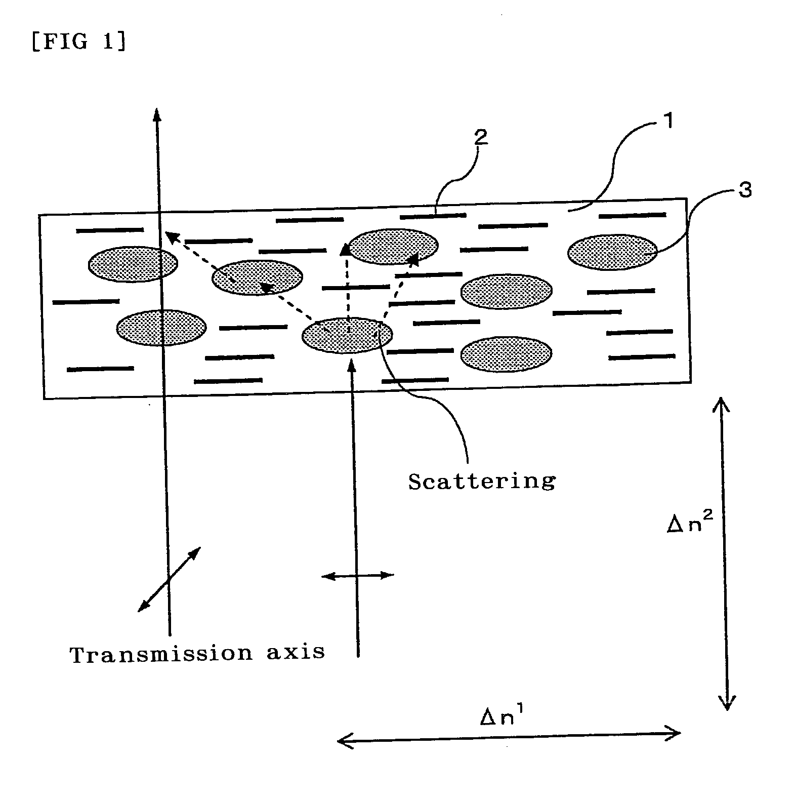
[0157]A polarizer was obtained using the process of Example 1 except that the ultraviolet irradiation process (vii) was not performed. It was demonstrated that the resulting polarizer showed anisotropic scattering and refractive index similarly to that of Example 1.

example 2

Preparation of Polarizing Plate

[0159]An adhesive composed of an aqueous solution of 7% by weight polyvinyl alcohol was applied to both sides of the polarizer obtained in Example 1, and then a triacetylcellulose film (80 μm in thickness), as transparent protective, whose surface to be adhered was saponified with an aqueous sodium hydroxide solution was adhered to each side of the polarizer to form a polarizing plate.


PUM

PropertyMeasurementUnit
refractive index differenceaaaaaaaaaa
refractive indexaaaaaaaaaa
transparentaaaaaaaaaa

Abstract

A method for manufacturing a polarizer of the invention, wherein the polarizer comprises a film that comprises: a matrix made of an optically-transparent resin containing a dichroic absorbing material; and minute domains that are made of an energy ray-curable birefringent material having liquid crystalline properties and are aligned and dispersed in the matrix; and comprising a process of applying energy rays for fixing the alignment of the birefringent material having liquid crystalline properties. A polarizer obtained by the method has a high transmittance and a high polarization degree, and being able to control unevenness of the transmittance in the case of black viewing.

Description

TECHNICAL FIELD[0001]The invention relates to a method for manufacturing a polarizer. The invention also relates to a method for manufacturing a polarizing plate. The invention also relates to a method for manufacturing a laminated optical film comprising a laminate of a polarizer or a polarizing plate and an optical film such as a retardation plate, a viewing angle compensating film, and a brightness enhancement film. Furthermore, this invention relates to an image display, such as a liquid crystal display, an organic electroluminescence display, a CRT and a PDP using the polarizer, the polarizing plate or the optical film concerned.BACKGROUND ART[0002]Liquid crystal display are rapidly developing in market, such as in clocks and watches, cellular phones, PDAs, notebook-sized personal computers, and monitor for personal computers, DVD players, TVs, etc. In the liquid crystal display, visualization is realized based on a variation of polarization state by switching of a liquid cryst...

Claims


Application Information

Patent Timeline
Patent Type & Authority Applications(United States)
IPC IPC(8): B29D7/01G02B1/08G02B5/30G02F1/13G02F1/1335
CPCG02B5/3008G02B5/30G02F1/13
Inventor FUTAMURA, KAZUNORIMIYATAKE, MINORUYOSHIOKA, MASAHIRO
Owner NITTO DENKO CORP
Why Eureka
Try Eureka