Radio Communication Apparatus and Peak Suppression Method

a radio communication and apparatus technology, applied in multiplex communication, orthogonal multiplex, baseband system details, etc., can solve the problem of generating transmission data sequences that provide maximum power, power consumption increases in the communication apparatus, and the efficiency of such power amplifiers is remarkably low in general, so as to reduce the peak-to-average power ratio without reducing transmission efficiency

Inactive Publication Date: 2008-09-25
PANASONIC CORP
View PDF3 Cites 32 Cited by
  • Summary
  • Abstract
  • Description
  • Claims
  • Application Information

AI Technical Summary

Benefits of technology

[0013]According to the invention, it is possible to reduce the peak-to-average power ratio without decreasing the transmission efficiency.

Problems solved by technology

But the efficiency of such a power amplifier is remarkably low in general, and power consumption increases in the communication apparatus.
The theoretical transmission peak power increases in proportion to the number of subcarriers, but actually the probability is extremely low of generating a transmission data sequence that provides the maximum power.
When peak clipping is performed, non-linear distortion occurs in a transmission signal, thereby degrading transmission characteristics of the transmission signal.
Further, since unnecessary, out-of-band emission occurs and needs to be removed with a band limit filter, a peak may occur again in the signal by allowing the signal through the band limit filter.

Method used


Image

  • Radio Communication Apparatus and Peak Suppression Method
  • Radio Communication Apparatus and Peak Suppression Method
  • Radio Communication Apparatus and Peak Suppression Method

Examples


embodiment 1

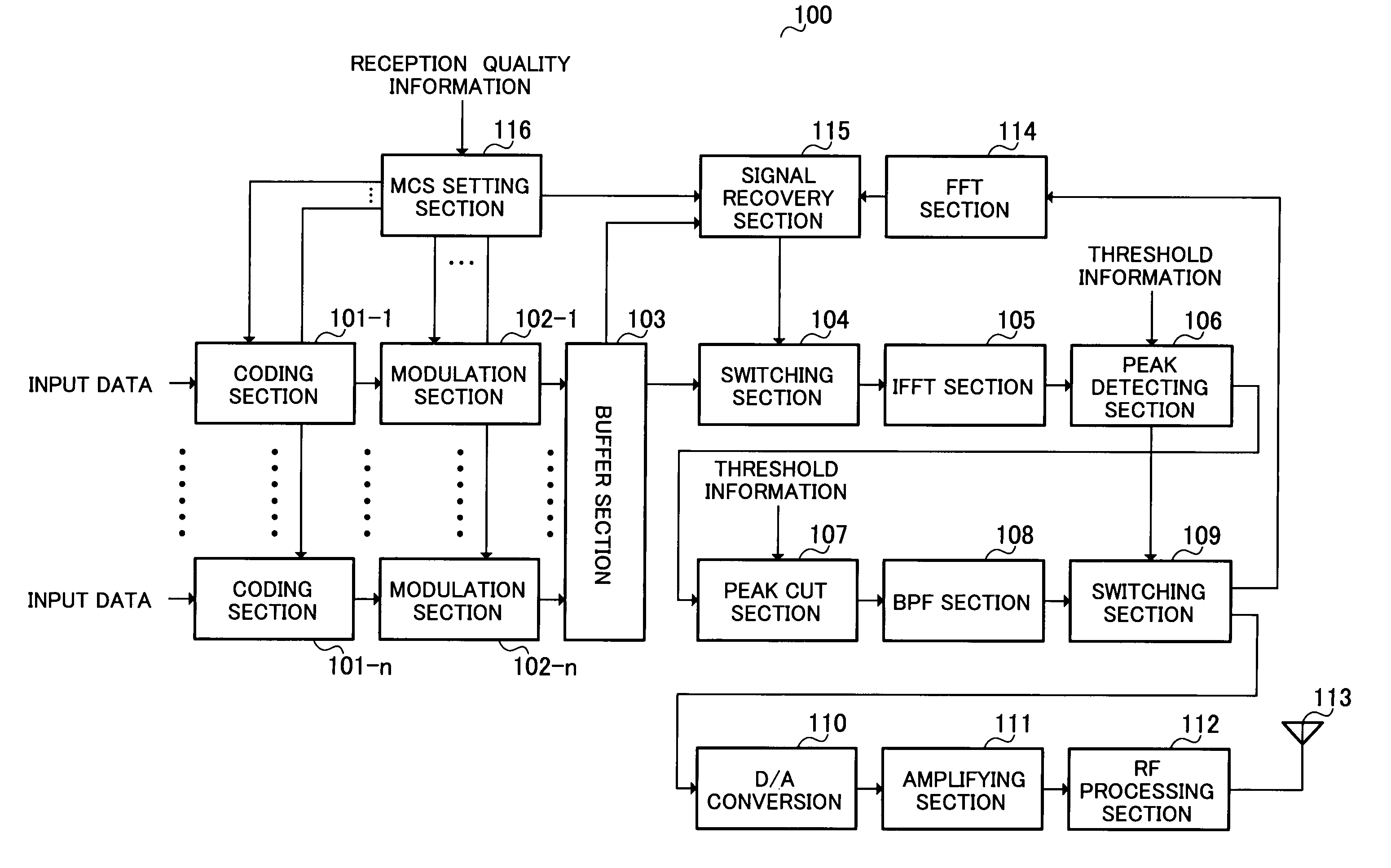
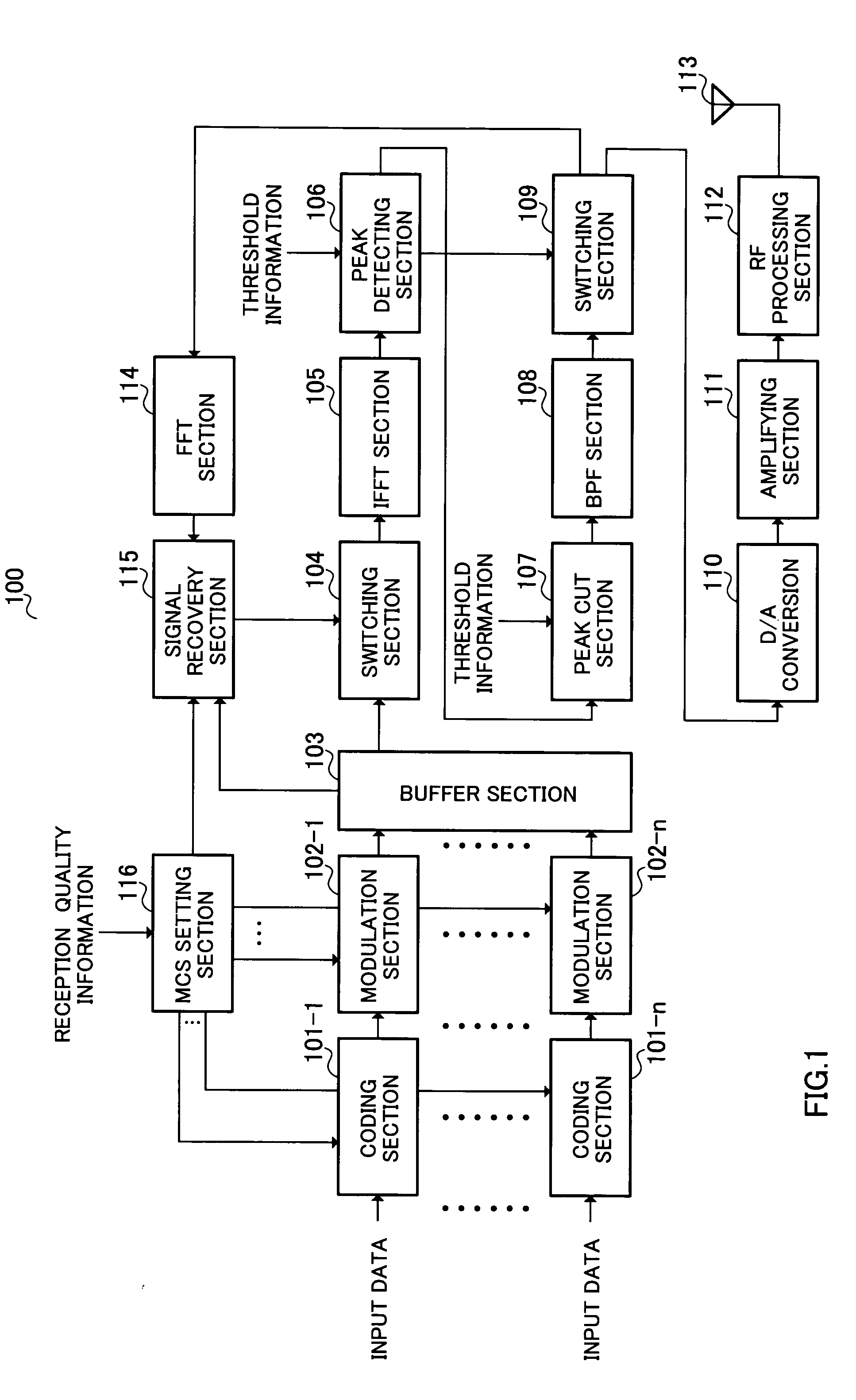
[0031]FIG. 1 is a block diagram illustrating a configuration of radio communication apparatus 100 according to Embodiment 1 of the present invention.

[0032]Based on control of MCS setting section 116, coding sections 101-1 to 101-n encode input data with predetermined coding rates for each subcarrier to output to modulation sections 102-1 to 102-n for each subcarrier, respectively.

[0033]Based on control of MCS setting section 116, modulation sections 102-1 to 102-n modulate the input data for each subcarrier input from coding sections 101-1 to 101-n with predetermined modulation schemes to output to buffer section 103, respectively.

[0034]Buffer section 103 outputs the input data input from modulation sections 102-1 to 102-n to switching section 104, while temporarily storing the input data input from modulation sections 102-1 to 102-n and outputting the stored input data to signal recovering section 115 at predetermined timing.

[0035]Switching section 104 switches between the input da...

embodiment 2

[0074]FIG. 10 is a block diagram illustrating a configuration of radio communication apparatus 1000 according to Embodiment 2 of the present invention.

[0075]As shown in FIG. 10, radio communication apparatus 1000 according to Embodiment 2 has puncturing section 1001 and peak suppression signal inserting section 1002 in radio communication apparatus 100 according to Embodiment 1 as shown in FIG. 1 without peak cut section 107, BPF section 108 and signal recovering section 115. In addition, in FIG. 10, the same sections as in FIG. 1 are assigned the same reference numerals to omit descriptions thereof.

[0076]Based on MCS information input from MCS setting section 116, puncturing section 1001 performs puncturing (thinning processing) on input data (elimination target transmission signal) assigned to part of subcarriers (low-transmission rate subcarriers) set for MCS indicative of lower transmission rates less than a predetermined threshold (third threshold) not to transmit, and outputs ...


PUM


Abstract

A radio communication apparatus enabling reduction in peak-to-average power ratio without decreasing the transmission efficiency. In this apparatus, buffer section 103 temporarily stores input data prior to peak suppression. Peak detecting section 106 detects a peak with an amplitude level not less than a threshold. Peak cut section 107 reduces the detected peak to the threshold. Switching section 109 is switched so that the peak suppressed signal is output to FFT section 114 when the peak is detected, while the peak suppressed signal is subjected to transmission processing when the peak is not detected. Based on MCS information, signal recovering section 115 eliminates a signal assigned to a subcarrier set for MCS of a high level, and as a substitute, assigns the signal prior to peak suppression stored in buffer section 103. MCS setting section 116 selects MCS based on reception quality information of a communicating party.

Description

TECHNICAL FIELD[0001]The present invention relates to a radio communication apparatus and peak suppressing method, and more particularly, to a radio communication apparatus that transmits transmission data with a plurality of subcarriers and a peak suppressing method.BACKGROUND ART[0002]Multicarrier transmission is of technique for transmitting data with a plurality of subcarriers of which the transmission rate is limited to such an extent that frequency selective fading does not occur, thereby improving the transmission efficiency, and enabling high-rate transmission as a result. In particular, OFDM (Orthogonal Frequency Division Multiplexing) modulation achieves the highest spectral efficiency among multicarrier transmission schemes, because its data subcarriers are orthogonal to one another. Therefore, OFDM system and OFDM-CDMA system obtained by combining OFDM and CDMA (Code Division Multiple Access) have been studied as a future high-rate transmission technique.[0003]As describ...

Claims


Application Information

Patent Timeline
Patent Type & Authority Applications(United States)
IPC IPC(8): H04B1/02H04L25/49H04L27/28H04J11/00H04L27/26
CPCH04L27/2624Y02B60/50H04L1/0026
Inventor EBIKO, KEISUKEUESUGI, MITSURU
Owner PANASONIC CORP
Why Eureka
Try Eureka