Vertical heat treatment system

a heat treatment system and vertical technology, applied in heat treatment equipment, furnaces, foundry moulding equipment, etc., can solve the problems of increasing energy utilization, castings may be exposed to the ambient environment of foundry or metal processing facilities, and castings tend to rapidly cool down, so as to improve the rate and efficiency

Inactive Publication Date: 2008-10-02
CONSOL ENG
View PDF101 Cites 10 Cited by
  • Summary
  • Abstract
  • Description
  • Claims
  • Application Information

AI Technical Summary

Benefits of technology

[0008]The heat sources further can include a variety of heating systems including conduction, convection, and other sources. In one embodiment, the heat sources can comprise high velocity forced air heating sources that direct turbulent, high velocity flows of heated air or other fluid media at velocities flows of approximately 2,500-4,000, up to approximately 40,000 feet per minute generally at distances of about 21-26 inches or less, and as short as 2-10 inches, from the castings. The velocity of the heated air flows and the distance of the applicator nozzles from the castings and their molds generally can be determined based upon the diameter and the configuration(s) of the nozzles being used (i.e., use of a series of spaced large, medium, or small diameter circular nozzles, slotted nozzles, or other configurations) and the positions / locations of the nozzles with respect to the centerlines of the castings as they are conveyed through the furnace chamber of the vertical heat treatment unit, which can be adjusted depending on sizes of the castings and the volume and velocity of the flames. The air flows further generally are at temperatures sufficient to promote heat treatment of the castings and additionally can assist with mold breakdown and core removal as the castings are moved through their vertical heat treatment units.
[0009]The vertical heat treatment unit further can include a conveying mechanism such as a rotary carousel that extends upwardly through the furnace chamber and includes a series of platforms, trays or racks on which a series of castings, i.e., 1-4 or more castings, are received. The castings typically will remain within in their molds, although they also can be previously removed from their molds prior to introduction into the vertical heat treatment unit. The castings generally will be fed into the furnace chamber by a manipulator, which can include a crane, forklift, or similar mechanism or can comprise the transfer robot of an associated loading carousel. As the castings are fed into the furnace chamber, the rotary carousel generally is operated in a up and down stepping motion, for example moving up one step to receive the castings and then downwardly two steps so as to ensure that a desired separation between incoming (colder) castings and outgoing (fully heated) castings is as large as possible. The vertical heat treatment unit can further include features that assist in removal and reclamation of the sand from the molds of the castings, which generally will be collected and reclaimed for reuse.
[0011]The vertical heat treatment unit of the present invention thus provides a significantly smaller footprint within the casting facility, which enables the vertical heat treatment unit to be placed in as close proximity as possible to the pouring stations. The vertical heat treatment unit of the present invention additionally can utilize existing robotic transfer mechanisms, lifts, or cranes for receiving the castings substantially directly from the pouring stations or from a loading carousel, with the time that the castings are exposed to the ambient environment of the metal processing facility thus being substantially minimized. As a result, the castings can be maintained at or above their process control temperature, as they are transferred from the pouring station to the vertical heat treatment unit of the present invention. In addition, the castings further can be monitored as they are removed from their pouring stations and transfered to their vertical heat treatment units, and additional heat added, such as by additional heating sources such as infrared lamps, heated fluid flows, inductive heaters, and / or other heat sources, as needed to substantially arrest cooling and / or maintain the temperature of the castings substantially at or above the process control temperature for the metal of the castings. Accordingly, the time required to heat treat the castings can be significantly reduced from approximately 2-6 hours down to as low as about 40 minutes to an hour.

Problems solved by technology

During the transfer of the castings from the pouring station to the heat treatment station, and especially if the castings are allowed to sit for any appreciable amount of time, however, the castings may be exposed to the ambient environment of the foundry or metal processing facility.
As a result, the castings tend to rapidly cool down from a molten or semi-molten temperature.
This results in greater utilization of energy and, therefore, greater heat treatment costs.

Method used


Image

  • Vertical heat treatment system
  • Vertical heat treatment system
  • Vertical heat treatment system

Examples


Embodiment Construction

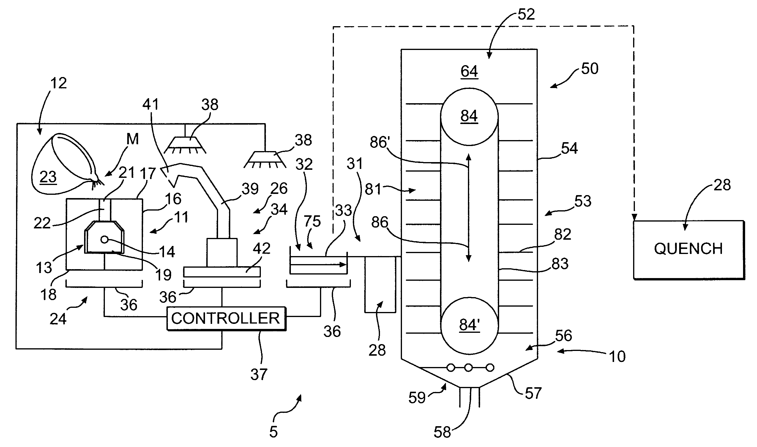
[0032]Referring now in greater detail to the drawings in which like numerals refer to like parts throughout the several views, FIGS. 2A-2B schematically illustrates an exemplary integrated metal processing facility or system 5 including the vertical heat treatment unit or “cell unit”10 according to the present invention for processing metallurgical castings. Metal casting processes generally are known to those skilled in the art and a traditional casting process will be described only briefly for reference purposes. It will be understood by those skilled in the art that the present invention can be used in any type of casting process, including metal casting processes for forming aluminum, iron, steel, and / or other types of metal and metal alloy castings. The present invention thus is not and should not be limited solely for use with a particular casting process or a particular type or types of metals or metal alloys.

[0033]As illustrated in FIG. 2A, a molten metal or metallic alloy ...


PUM

PropertyMeasurementUnit
timeaaaaaaaaaa
temperaturesaaaaaaaaaa
temperatureaaaaaaaaaa

Abstract

A system and method for forming and heat treating metal castings is provided with a vertical heat treatment unit positioned adjacent and downstream from a pouring station at which a series of molds are filled with a molten metal to form the castings. The vertical heat treatment unit includes a vertically oriented furnace chamber in which the castings are received, and which has a reduced footprint to reduce the manufacturing floor space required for the vertical heat treatment unit, and to enable the vertical heat treatment unit to be positioned in close proximity to the pouring station.

Description

CROSS REFERENCE TO RELATED APPLICATIONS[0001]The present patent application claims the benefit of the filing date of U.S. provisional patent application No. 60 / 908,743, filed Mar. 29, 2007 and U.S. provisional patent application No. 60 / 909,048, filed Mar. 30, 2007, according to the statutes and rules governing provisional patent applications, particularly USC §119(e)(1) and 37 CFR §1.78(a)(4) and (a)(5). The specification and drawings of the provisional patent application are specifically incorporated fully herein by reference.BACKGROUND OF THE INVENTION[0002]Traditionally, in conventional processes for forming metal castings, a mold, such as a metal die or sand mold having an interior chamber with the exterior features of a desired casting defined therein, is filled with a molten metal. A sand core that defines interior features of the castings is received and / or positioned within the mold to form the interior detail of the casting as the molten metal solidifies about the core. Aft...

Claims


Application Information

Patent Timeline
Patent Type & Authority Applications(United States)
IPC IPC(8): B22D45/00B22D19/00
CPCB22D47/02C21D9/005F27B9/16F27B9/243B22D47/00B22D45/00C21D9/0006
Inventor CRAFTON, SCOTT P.CRAFTON, PAUL M.FRENCH, IANKNOBLOCH, VOLKER
Owner CONSOL ENG
Why Eureka
Try Eureka