
Mounting board including a flat-type electrical element and capable of being reduced in size, and lead-attached electric element that is flat in shape and has a lead bonded to each electrode face

a technology of mounting board and electrode, which is applied in the direction of fixed connections, printed circuit aspects, printed circuit manufacturing, etc., can solve the problems of troublesome difficult to bring the soldering iron into contact with the solder bond, and difficulty in detachment of flat-type batteries after detachment, so as to facilitate rework, increase the envelope volume of the mounting board, and effectively utilize the thickness of the pc board

Inactive Publication Date: 2008-10-02
FDK CORP +1
View PDF5 Cites 6 Cited by
  • Summary
  • Abstract
  • Description
  • Claims
  • Application Information

AI Technical Summary

Benefits of technology

[0012]The present invention has been achieved in view of the above problems, and an aim thereof is to provide a lead-attached electrical element and a mounting board to which the lead-attached electrical element is mounted, both of which contribute to a reduction in the size of the mounting board as well as facilitate rework such as detaching the electrical element when necessary.
[0020]Providing the aperture in the portion of the lead that is to be bent, before the bending is performed, enables improving mass-productivity and yield.

Problems solved by technology

However, performing such rework has the following problems.
In conventional cases in which a flat-type battery is directly soldered to a conductive land on a mounting board, it is very troublesome to detach the flat-type battery after it has been mounted to the mounting board.
Specifically, since the flat-type battery has been mounted by being soldered directly to the PC board, it is difficult to bring the soldering iron into contact with the solder bond in order to melt the solder, which makes detaching the flat-type battery very troublesome.
Rework is therefore difficult in the case of mounting boards having this type of structure.

Method used


Image

  • Mounting board including a flat-type electrical element and capable of being reduced in size, and lead-attached electric element that is flat in shape and has a lead bonded to each electrode face
  • Mounting board including a flat-type electrical element and capable of being reduced in size, and lead-attached electric element that is flat in shape and has a lead bonded to each electrode face
  • Mounting board including a flat-type electrical element and capable of being reduced in size, and lead-attached electric element that is flat in shape and has a lead bonded to each electrode face

Examples


embodiment 1

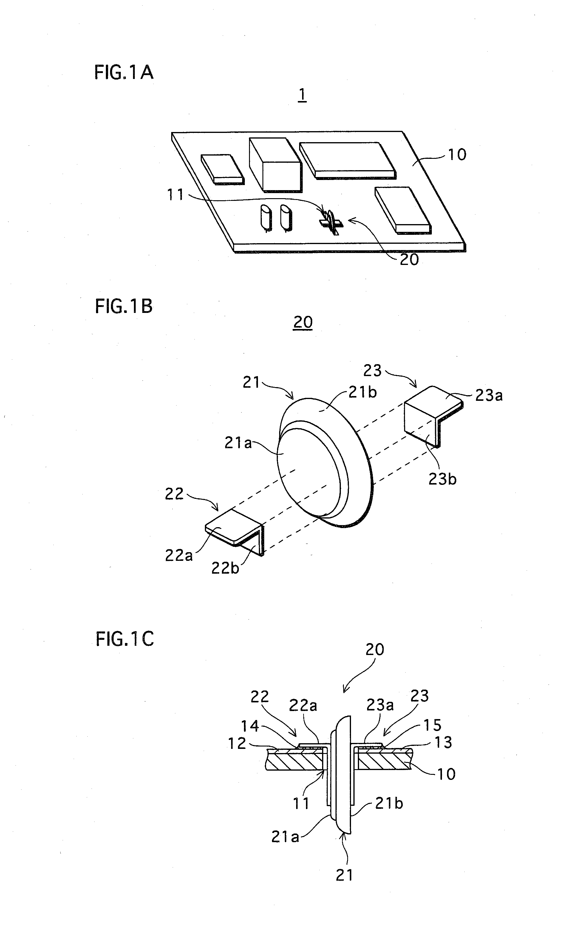
[0033]As shown in FIG. 1A, a mounting board 1 of the present embodiment is constituted from a PC (printed circuit) board 10 and a lead-attached coin-type battery 20.

[0034]The PC board 10 is made of a composite material. An aperture 11 has been provided in a main face of the PC board 10 at a predetermined position for the insertion of the lead-attached coin-type battery 20.

[0035]As shown in FIG. 1B, the lead-attached coin-type battery 20 is constituted from a coin-type battery 21 and two leads 22 and 23 bonded thereto.

[0036]In the present embodiment, the coin-type battery 21 has a known structure (e.g., a coin-type lithium secondary battery having a thickness of 1.0 [mm] and a diameter of 4.8 [mm]).

[0037]As shown in FIG. 1B, the coin-type battery 21 is a flat disk, where one main face is a cathode face 21a and the other main face is an anode face 21b.

[0038]The leads 22 and 23 are each an elongated plate made of a metal material such as phosphor bronze, and are constituted from main ...

embodiment 2

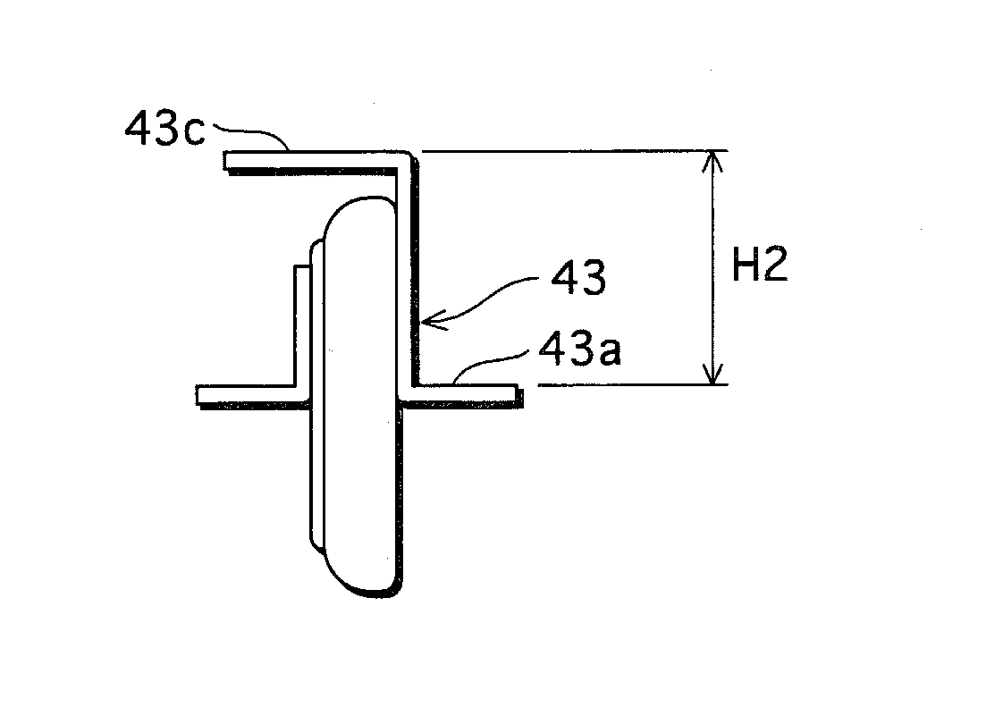
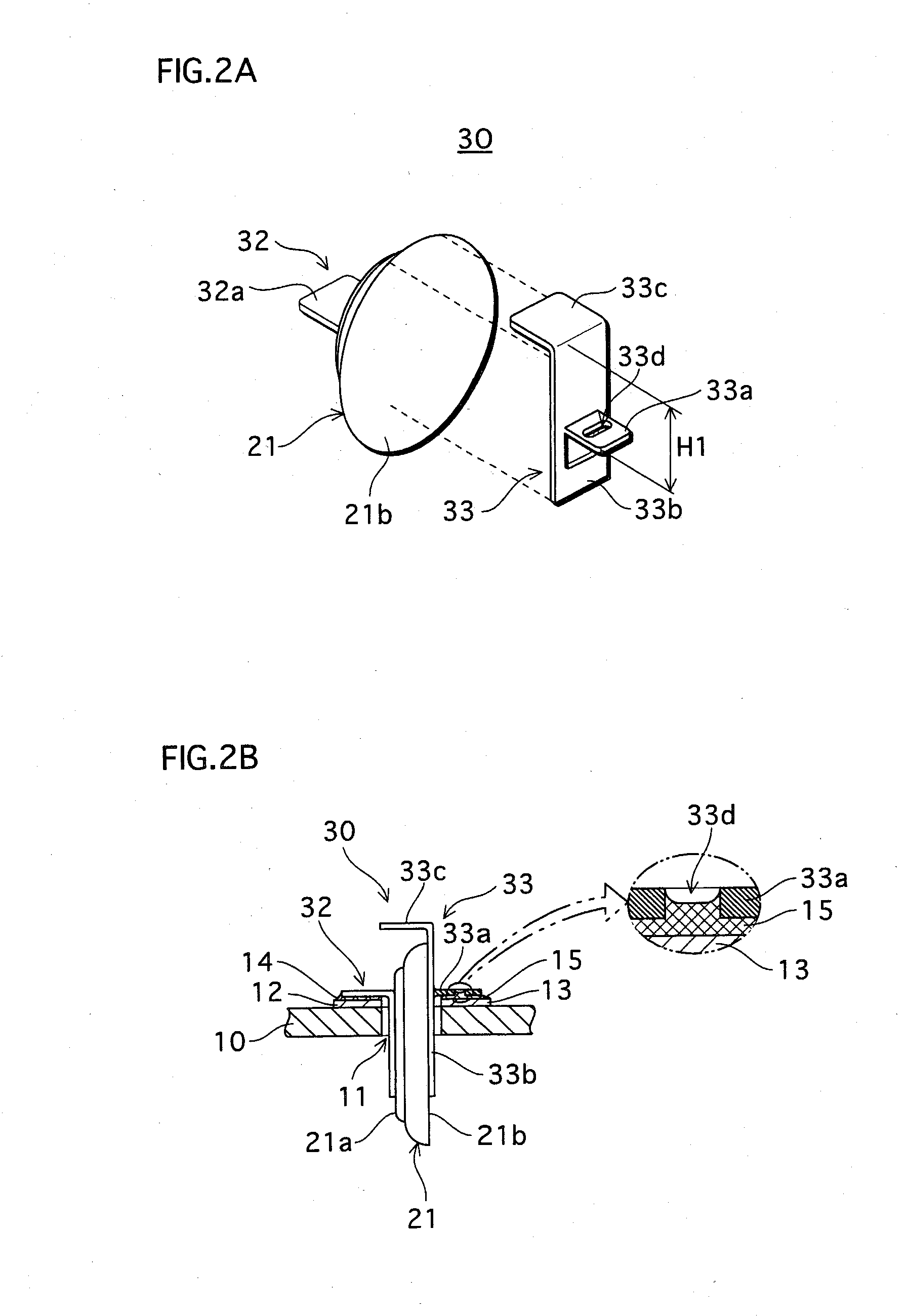
[0057]Embodiment 2 differs from embodiment 1 with respect to the following three points. Firstly, the bent portion of one of the leads is formed by cutting and bending a portion of a rectangular plate. Secondly, an aperture is provided in this bent portion. Thirdly, this lead extends beyond the outer periphery of a main face of the coin-type battery, and a top-plate portion is provided by bending the extending portion of the lead.

[0058]A lead 33 is constituted from a rectangular plate 31, and one end of the rectangular plate 31 is bent as shown in FIGS. 3A and 3B. As a result, as shown in FIG. 2A, the lead 33 has a top-plate portion 33c that is outward with respect to the outer periphery of the anode face 21b of the coin-type battery 21, in a direction along the anode face 21b. As shown in FIG. 2B, the -top-plate portion 33c is substantially orthogonal to the anode face 21b of the coin-type battery 21. This structure enables the top-plate portion 33c to be used as a grip / handle. As ...

embodiment 3

[0072]A main feature of the present embodiment is that the angle between the bent portion of the leads and the cathode face or anode face of the coin-type battery (i.e., the angle between the main face of the PC board 10 and the cathode face or anode face) is different from embodiment 1.

[0073]In the present embodiment, as shown in FIG. 7, an angle θ1 between the main face of the PC board 10 and the cathode face 21a of the coin-type battery 21 has been set to an acute angle, and an angle θ2 between the main face of the PC board 10 and the anode face 21b of the coin-type battery 21 has been set to an obtuse angle (note that the sum of angle 741 and angle θ2 is set to equal 180[°], and bent portions 62a and 63a both have horizontal surfaces).

[0074]As a result of this innovation in the present embodiment, the cathode face 21a and anode face 21b of the coin-type battery 21 are inclined with respect to the main face of the PC board 10. Even if, for example, the coin-type battery 21 has a ...


PUM


Abstract

A lead-attached electrical element and a mounting board to which the lead-attached electrical element is mounted both contribute to a reduction in the size of the mounting board as well as facilitate rework. The lead-attached electrical element is constituted from an electrical element and two leads. Each lead includes a main portion which is bonded to a respective electrode face of the electrical element, and a bent portion which is inclined with respect to the main portion. The mounting board is constituted from a PC (printed circuit) board and the lead-attached electrical element. Two conductive lands are provided on a surface of the PC board. The lead-attached electrical element has been inserted into an aperture in the PC board, and bent portions of the leads attached to the electrical element are bonded to the conductive lands so that the electrical element is suspended in the aperture by the leads.

Description

[0001]This application is based on an application No. 2007-084112 filed in Japan, the content of which is hereby incorporated by reference.BACKGROUND OF THE INVENTION[0002]1. Field of the Invention[0003]The present invention relates to a mounting board composed of a PC (printed circuit) board on which a flat-type electrical element is mounted, and a lead-attached electrical element that is flat in shape and has a lead bonded to each electrode face. The present invention relates particularly to technology for an improved structure for mounting the electrical element to the PC board, taking into account reductions in size.[0004]2. Description of the Related Art[0005]Conventionally, mounting boards including a microcomputer, memory, etc. often have a flat-type electrical element such as a battery or capacitor mounted thereon as a backup power supply. The term “flat-type electrical element” includes so-called “coin-type” and “button-type” electrical elements. Generally, one end of a lea...

Claims


Application Information

Patent Timeline
IPC IPC(8): H01R12/06H05K1/00H01R12/51
CPCH05K1/182H05K3/3421H05K2201/09836H05K2201/10037H05K2201/10484H05K2201/10651H05K2201/10856H05K2203/0195H05K2203/082H01R12/7082
Inventor OZAKI, HIROTOSHIMORIMOTO, AKIKOYAMASHITA, TETSUYA
Owner FDK CORP
Learn More