Biological Saw Sensor

Inactive Publication Date: 2008-10-02
MNT INNOVATIONS
View PDF4 Cites 20 Cited by
  • Summary
  • Abstract
  • Description
  • Claims
  • Application Information

AI Technical Summary

Benefits of technology

[0023]Where a disposable sensor unit is arranged in a microfluidic surface the known quantity of the non viable form of the target species may be placed in the microfluidic channel upstream of the SAW sensor. The device may include a reservoir for distilled water which is used to flush the non viable material and flow it across the sensor to obtain the first calibrating measurement. Only the quantity of the non v

Problems solved by technology

This system and most prior art systems have the problem that quantitative measurements are comp

Method used


Image

  • Biological Saw Sensor
  • Biological Saw Sensor
  • Biological Saw Sensor

Examples


Example

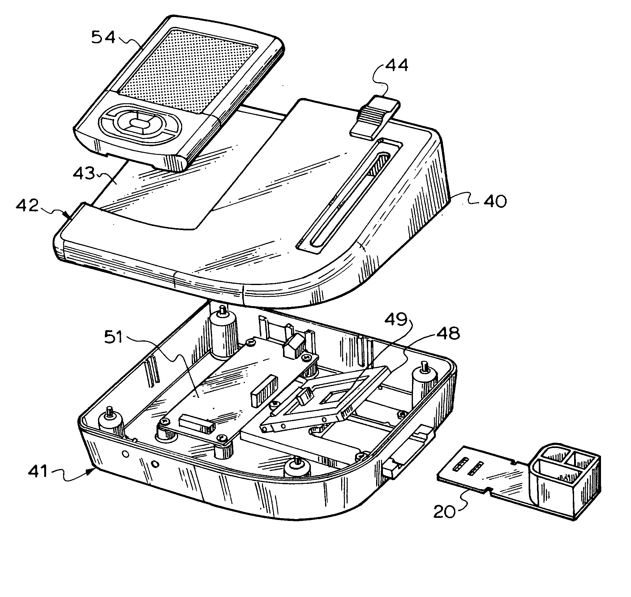
[0029]FIG. 4 illustrates an exploded view of a second embodiment of this invention;

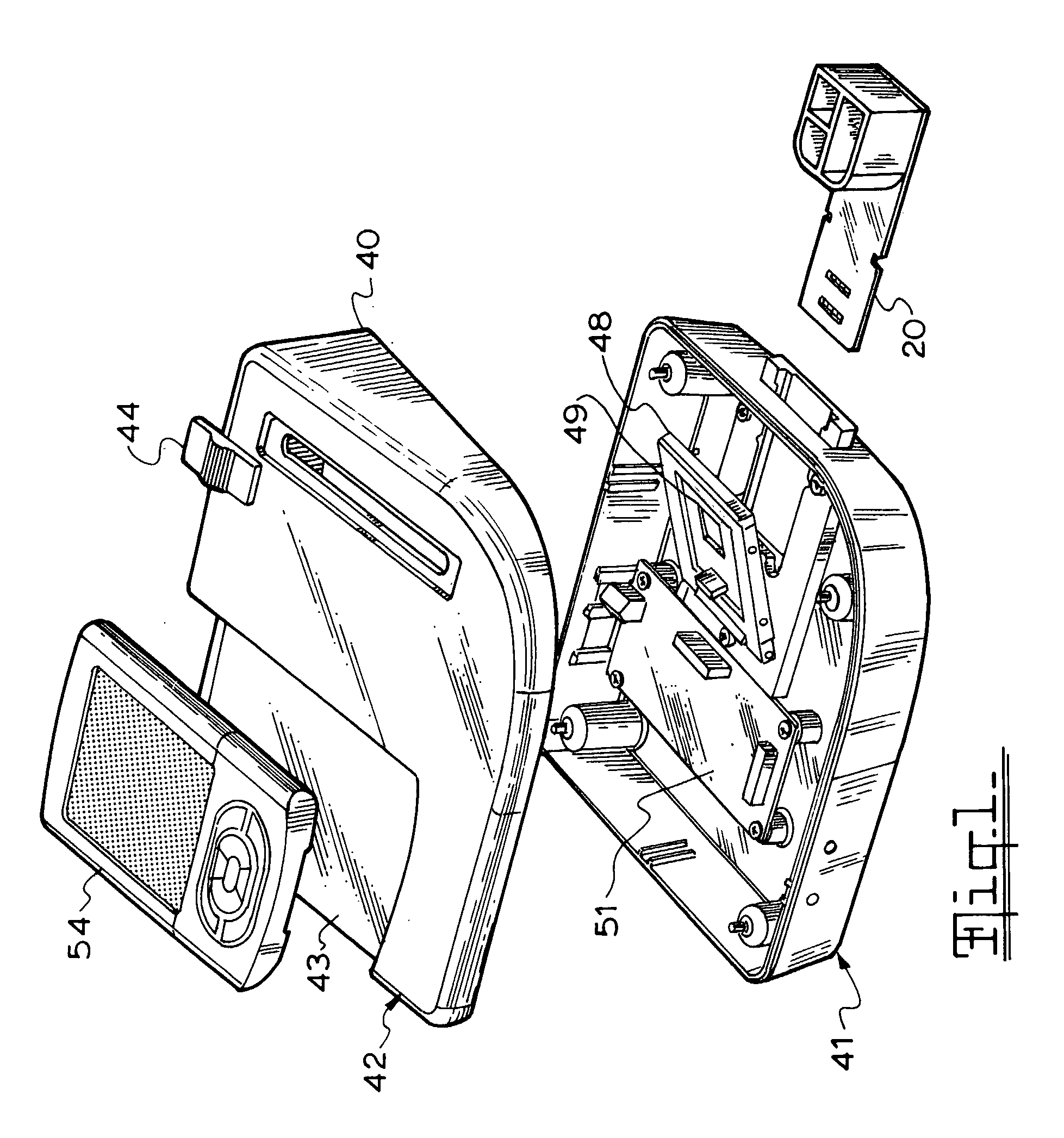
[0030]FIG. 5 is a reverse view of the embodiment of FIG. 4 shown in the operative orientation;

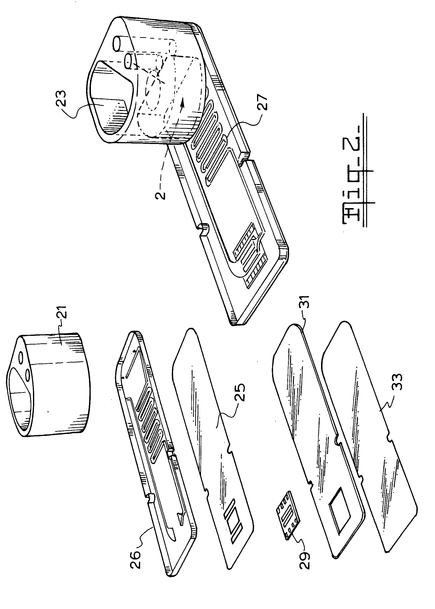
[0031]FIG. 6 illustrates the sample filtration unit of this invention;

[0032]FIG. 7 illustrates an exploded view of the sample filtration unit of FIG. 6.

[0033]The system consists of the detector unit 20 the reader unit 40 and a PDA 60.

[0034]The reader consists of a bottom unit 41 and a cover 42. the cover incorporates a docking bay 43 for the PDA 60 and also incorporates a slide button 44 for locking the detector unit 20 into electrical contact with the reader.

[0035]The docking recess 47 accommodates the detector unit 20 when it is slid into the recess. The spring hinged block 48 contains SAW printed circuit board (PCB) 49 for reading the SAW sensor on the detector unit. The SAW PCB contains spring pins for connection to the SAW sensor on the detection unit 20 as well as signal amplification circuitry and an i...


PUM


Abstract

Analysing fluid samples for target biological or chemical species comprising a detector unit with a body incorporating a SAW sensor (29) for said target species, in a microfluidic channel (27) and a reader unit adapted to receive the detector unit. The reader unit includes electrical contacts with said SAW sensor and a processor to analyse the sensor signals to determine if the target is present. The detector unit includes a storage reservoir (23) for the calibrating and sample solutions arranged so that the fluid flows through the microfluidic channel over the SAW sensor to a storage reservoir. The sensor is calibrated by using a first liquid having a known quantity of a form of the target species to provide a first frequency change and then a sample solution to be measured and measuring a second frequency change and using the first and second measurements to calibrate the sensor and determine the quantity of the target in the sample solution.

Description

[0001]This invention relates to biological sensors and in particular a sensor system that can be used to quickly and conveniently identify a variety of microorganisms or biological species.BACKGROUND TO THE INVENTION[0002]The detection of pathogens or microorganism contamination as a means of diagnosis or as a means of monitoring quality of food stuffs usually involves taking a sample and conducting analysis in a laboratory. Portable analytical tools have been proposed which use microfluidic devices that can handle small volumes. Many of these use analytical processes such as PCR or bio beads. U.S. Pat. No. 6,408,878 and WO 02 / 081729 disclose PCR micro fluidic reactors.[0003]USA application 2004 / 0115094 discloses a microfluidic analysis kit which includes a solvent and waste store on a microfluidic chip.[0004]Various analytical tools have been proposed for identifying biological species including Matrix assisted laser desorption / ionization (MALDI) and in association with time of fli...

Claims


Application Information

Patent Timeline
IPC IPC(8): G01N37/00B01J19/00C12M1/34B01L11/00B01L99/00
CPCG01N29/022G01N29/036G01N29/222Y10T436/10G01N2291/02466G01N2291/0256G01N2291/0423G01N29/226
Inventor BARKER, JARRODHOLTHOUSE, SHAUNSOLOMON, MATHEW
Owner MNT INNOVATIONS
Why Eureka
Try Eureka