
High Turbulence Mill and Bi-Negative Pressure Turbine Thereof

a high-turbulence mill and turbine technology, applied in the direction of cocoa, grain milling, solid separation, etc., can solve the problems of difficult to solve the problem of conglomeration of such materials, no suitable technology or equipment for producing such materials, and lack of desired effect when in use. achieve the effect of high efficiency

Inactive Publication Date: 2008-10-09
YANG FUMAO +1
View PDF4 Cites 18 Cited by
  • Summary
  • Abstract
  • Description
  • Claims
  • Application Information

AI Technical Summary

Benefits of technology

[0007]In view of the current situation as well as the technical problems existing in the research and development of supermicro powder materials and nanomaterials and their application, an object of the present invention is to provide a pulverizing or grinding device which is better than conventional pulverizing or grinding equipments, and is able to produce supermicro powder and nano powder with a high efficiency.
[0022]The high turbulence mill according to the present invention utilizes a high turbulence, which is generated as a result of a high speed rotation of the specifically designed bi-negative pressure and dual vortex turbine, to pulverize or grind materials. A high turbulence is occurred when Renault number Re>1.5×10⁵. The Renault number of the turbulence mill of the present invention has ° reached a level of Re>6.6×10⁵, by which the generation of a high turbulence is assured.
[0023]An important characteristic of turbulence is irregularity, i.e. an irregular and random movement composed of different sized vortexes. It essential characteristic is random pulses. Its speed field and pressure field are random not only in respect to time domain but also in respect to space domain. Another crucial characteristic of turbulence is the diffusion of energy. Vortexes in the turbulence may lead to energy exchange within the fluid flow, that is, mass points with higher energy pass kinetic energy to mass points with lower energy while mass points with lower energy also affect mass points with higher energy. As a result, such a diffusion effect enhances the transfer of kinetic energy.
[0024]When solid materials to be crushed are exposed to a high turbulence field, a gas-solid two-phase flow will be formed. The turbulence energy from the turbine is transferred gradually from larger vortexes to smaller vortexes by an inertia effect generated by a rotation at a high speed. As a result, materials are effectively crushed due to violent impact, self-grinding effect, shear effect generated due to the complicated turbulence.
[0025]The high turbulence mill achieves a breakthrough on the pulverizing mechanism, and possesses specific technical features such as bi-negative pressure, dual vortexes, high turbulence and high centrifugal force, and also possesses beneficial effects such as energy saving, capable of producing supermicro (sub-micrometer) powders and perfect environmental protection performance, thereby solving many shortcomings of currently used mechanical pulverizing method which have been addressed by industries and experts in the art for many years.
[0027]The high turbulence mill of the present invention offers a feasible way to realize a mass production of supermicro materials and nanomaterials.

Problems solved by technology

It is said that supermicro materials are of a bottle-neck material from superfine materials to nanomaterials, but there seems to have no suitable technology or equipments for producing such materials.
Some investigations claim that nanomaterials produced by chemical methods usually have changes in physical property thereof, and thus can not exhibit a desired effect when in use.
Moreover, it is difficult to solve the problem of conglomeration of such materials.
Therefore, the production efficiency is low and the production cost is high, which leads that nanomaterials can only be produced in a small amount in laboratories and cannot be made in industry.

Method used


Image

  • High Turbulence Mill and Bi-Negative Pressure Turbine Thereof
  • High Turbulence Mill and Bi-Negative Pressure Turbine Thereof
  • High Turbulence Mill and Bi-Negative Pressure Turbine Thereof

Examples


Embodiment Construction

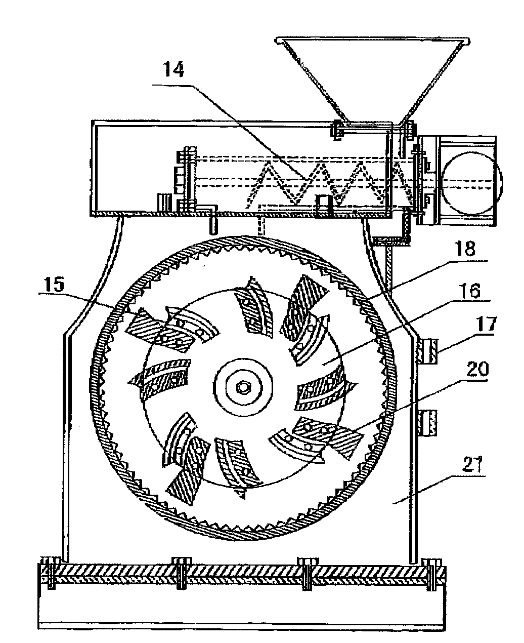
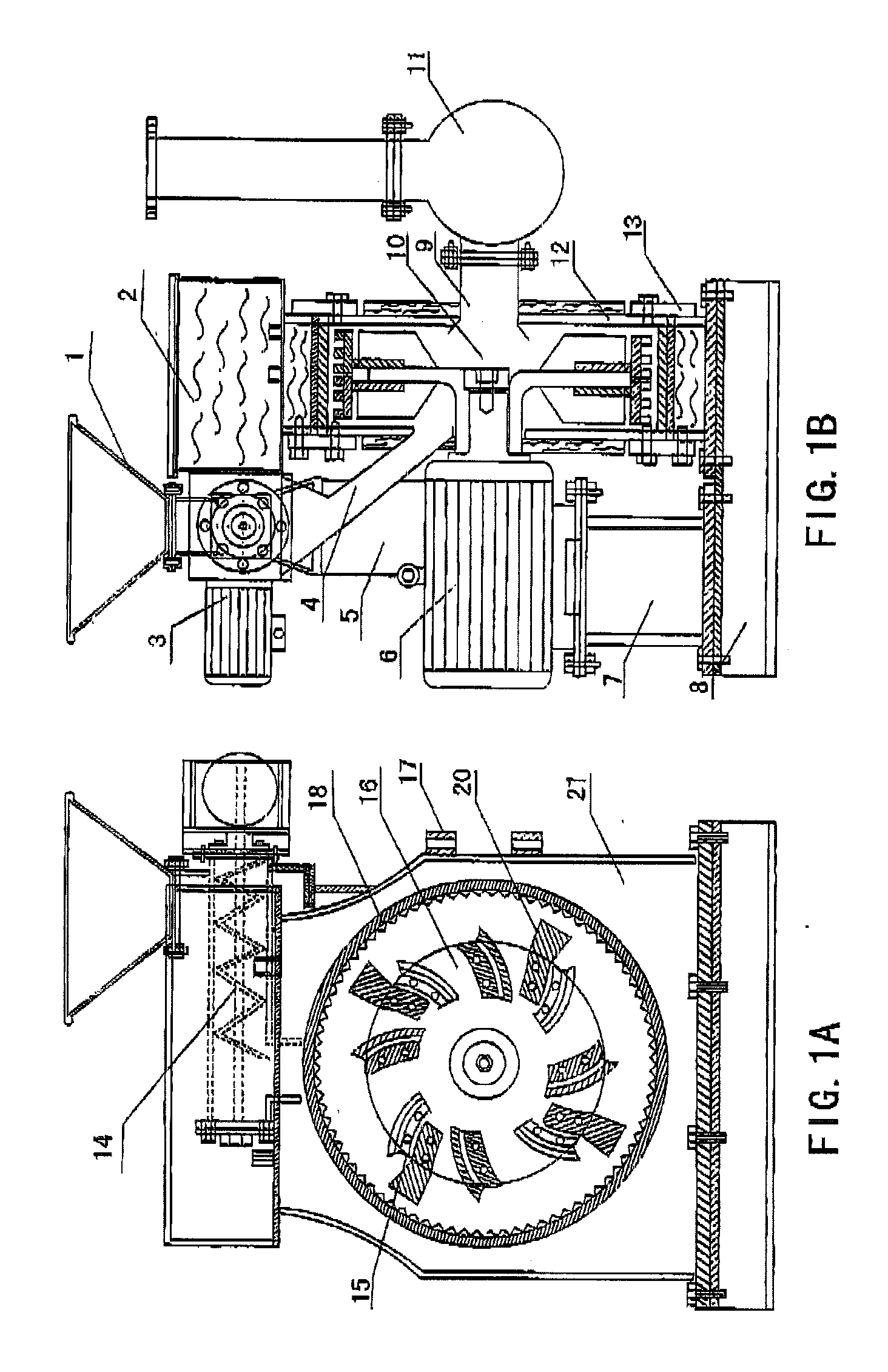
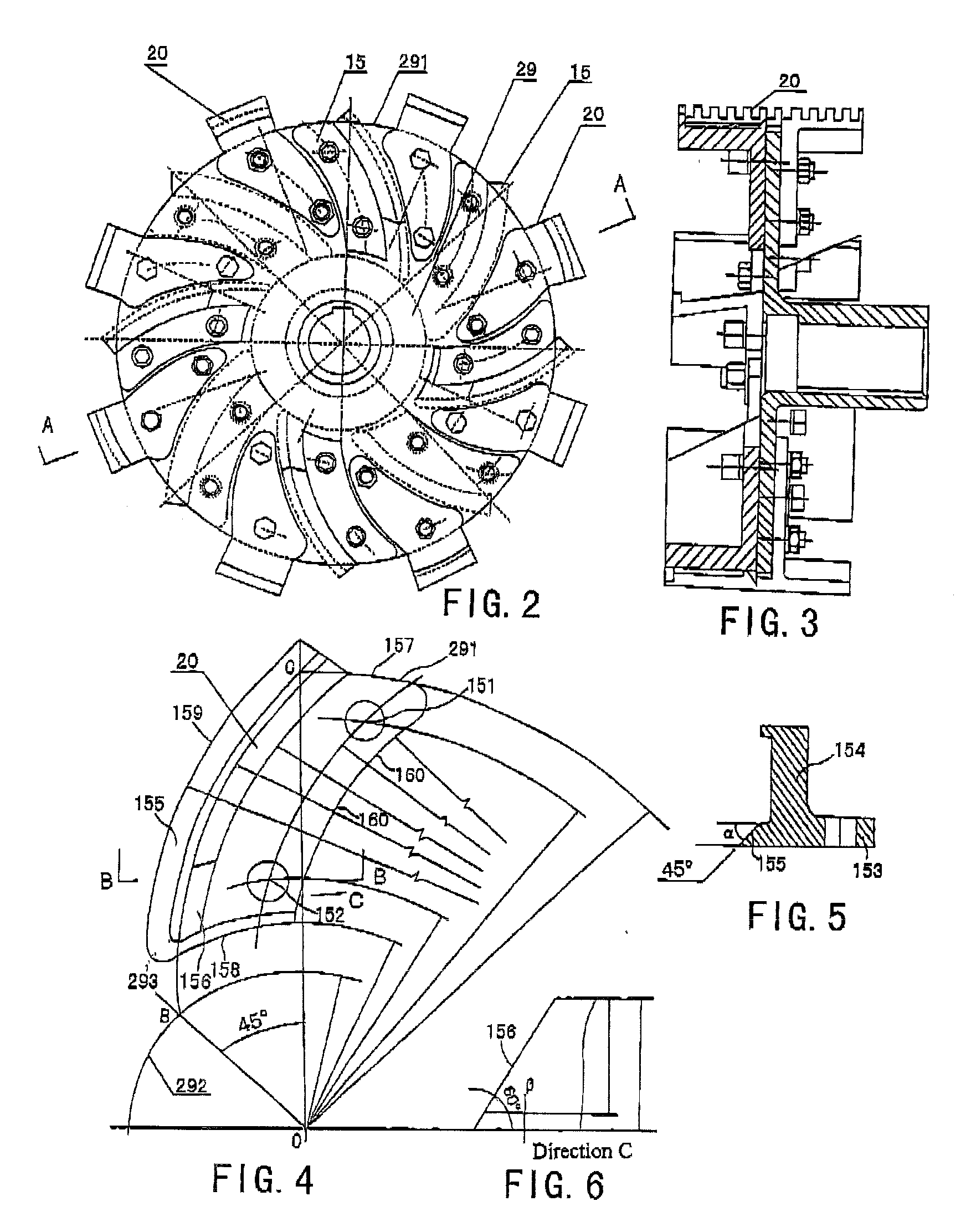
[0075]A high turbulence mill according to the present invention is shown in FIGS. 1A and 1B, which mainly includes a base 8, a grinding casing 21, a driving device 6, a spiral conveyer 14 and a control device and the like. The entire high turbulence mill is a horizontal one. The driving device 6 is mounted onto the base 8 via supporting frame 7, and comprises a motor and a driving shaft connected to an output shaft of the motor. In the embodiment of the present invention, the motor is preferably a variable frequency motor, and the driving shaft is connected to the variable frequency motor to drive a bi-negative pressure turbine 16 within the grinding casing 21.

[0076]The spiral conveyer 14 is secured onto the base 3 through a supporting frame 5, and positioned above the grinding casing 21. A hopper 1 is arranged over the spiral conveyer 14, for transferring the materials to be crushed into the spiral conveyer 14. The spiral conveyer 14 is driven by a speed adjustable motor 3.

[0077]A ...


PUM


Abstract

A high turbulence mill used for producing supermicro powder and nanomaterials includes: a driving device provided on a base; a hollow grinding casing having a toothed ring-shaped guide stator fixed to an inner circumference thereof; a bi-negative pressure turbine rotatably mounted within the grinding casing; a hopper for delivering materials into the grinding casing via a material feeding pipe; a material discharging pipe communicated with the grinding casing for discharging pulverized products; and a control device for electrically controlling the high turbulence mill. When the specifically designed bi-negative pressure turbine spins at a high speed within the grinding casing under the driving operation of the motor, strong vortexes and high turbulence will be formed in the grinding casing, and thus a gas-solid two-phase flow is formed. Under the high turbulence, the materials are subjected to violent self-grinding effect, strong impact and strong shear force, and then an accelerated and effective pulverization of the materials is obtained.

Description

FIELD OF THE INVENTION[0001]The present invention relates to a device for producing supermicro powder and nanomaterials, and more particularly, to a high turbulence mill for grinding materials into supermicro powder and a bi-negative pressure turbine adapted for the high turbulence mill. The fields into which the high turbulence mill could be applied not only include high-tech fields such as military, aerospace industries, but also include many other fields such as microelectronics, new drugs, new material, new energy, as well as general chemical, mechanical, metallurgy, environmental protection, food and daily-use products industries.BACKGROUND OF THE INVENTION[0002]For domestic and overseas science and technology domain, the technique for producing super find powder could be deemed as a “trans-centry” high-tech.[0003]Rapid development in science and technology endows supermicro materials and nanomaterials with wide application prospects, and also the research regarding supermicro ...

Claims


Application Information

Patent Timeline
IPC IPC(8): B02C13/12B02C13/20B02C13/26B02C13/08B02C19/20
CPCB02C13/08B02C13/2804B02C13/282
Inventor YANG, FUMAOLIU, XINGFA
Owner YANG FUMAO
Learn More