Method for improved rotational alignment in joint arthroplasty

a technology of rotational alignment and joint arthroplasty, which is applied in the field of improving rotational alignment in joint arthroplasty, can solve the problems of increasing the “quadriceps” (, difficult to accurately localize the epicondylar axis using these various techniques), and the femoral component rotational alignment is particularly problematic. , to achieve the effect of improving the accuracy of rotational alignmen

Inactive Publication Date: 2008-10-09
THE BOARD OF TRUSTEES OF THE LELAND STANFORD JUNIOR UNIV
View PDF10 Cites 83 Cited by
  • Summary
  • Abstract
  • Description
  • Claims
  • Application Information

AI Technical Summary

Benefits of technology

[0012]The invention includes methods and systems to record the alignment axis of two bones meeting at a joint, prior to or during surgery for artificial joint implantation, by using the relative movement of a third bone with reference to the two major bones meeting at the joint. When applied to knee replacement surgery, the alignment axes of the femur, and the tibia at the knee are determined using the movement of the patella. The method can also be used for aligning the femur and tibia using the talus and calcaneus. Similarly, the hip joint can be aligned using the movement of the tibia with respect to the femur. The relative movement of the bones is tracked using either optical sensors, electromagnetic sensors, some other sensor, or medical images. The data on relative movement of the bones can be used as it is or after smoothing using a suitable algorithm. The curve traced by the third bone on the first or the second bone can be fitted to a suitable function such as a spline function or a polynomial function. Optionally, two or more rotational alignments axes, obtained according to two or more different techniques, may be combined to generate a rotational alignment axis that provides improved accuracy in rotational alignment.

Problems solved by technology

It has been shown in a previous study that rotational alignment of the femoral component is particularly problematic (Berger et al., 1998).
Malalignment of femoral component rotation can lead to a number of complications.
Internal rotation of the femoral component causes a shift into valgus alignment with flexion and also an increase in the “quadriceps” (Q) angle with deleterious effects on patella tracking.
It has been reported that accurate localization of the epicondylar axis using these various techniques is difficult even under normal conditions when the joint is not diseased and has not been previously operated on.
It is particularly difficult in the diseased or previously operated joint when external bony landmarks are distorted or no longer available.
This level of intrusion is not desirable, because it increases the risk of fat embolism and unnecessary blood loss in the patient.
The Robodoc system has been tested in the operating room and has produced accurate bone resections, but the system has several important limitations.
It is expensive, for example, and must be operated by a specially-trained technician.
It also adds substantially to OR time, increasing the cost of using the system.
Another problem is that the Robodoc system uses a pin-based registration method, which increases patient trauma and lengthens the patient's rehabilitation time.
However, the problem of identifying the correct rotational axis is not addressed in these inventions and this aspect is still left to the judgment and skill of the surgeon.
Computer navigation promises to improve alignment of total knee replacement components, but at present, experimental work by several experts shows that the techniques that are used for femoral rotational alignment are no better than traditional techniques that do not use computer navigation technology (Siston et al., 2005).
(2006) suggest that a navigation system that relies on digitization of landmarks to establish a rotational alignment axis does not provide a more reliable means of rotational alignment than using traditional TKA instrumentation.
When the tibial tubercle is referenced by the navigation system to establish tibial component rotational alignment, the resultant alignment axes are significantly less reliable than when traditional instrumentation is used.
Existing computer based navigational techniques, therefore, do not provide a more reliable means of rotational alignment as compared with traditional techniques.
One of the main reasons for difficulties in alignment, even when computer navigation and precision are involved, is the variability in joint geometry and bone shape between individuals that makes a generalized numerical scheme inapplicable.

Method used


Image

  • Method for improved rotational alignment in joint arthroplasty
  • Method for improved rotational alignment in joint arthroplasty
  • Method for improved rotational alignment in joint arthroplasty

Examples


Embodiment Construction

[0022]The invention is a method to record the alignment axis of two bones prior to or during surgery for artificial joint implantation by using the relative movement of a third bone with reference to the two major bones meeting at the joint.

[0023]During knee arthroplasty, after the knee has been exposed and trackers have been placed in the femur and the tibia, but before any bone cuts are made, the path that the patella tracks with respect to the femur when the knee is flexed and / or extended is recorded. To do this, the surgeon reduces the patella in the native trochlear groove.

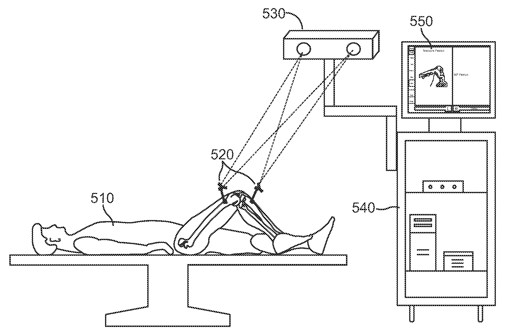
[0024]Total knee arthroplasty according to the present invention is shown in FIGS. 5A and B. The right knee of a subject 510 is shown set up for the surgical procedure in FIG. 5A. Reference frames 520 are attached to the femur and the tibia to enable the optical tracking system 530 to reference their respective positions. Details of the reference frames 520 are shown in FIG. 5B, where the three-armed frames 5...


PUM


Abstract

A method for improved rotational alignment of the bones in joint surgery is described. The method involves the tracking of the relative motion of a third bone in with respect to the movement of the first and second bone. In one aspect of the invention, the motion of the patella is used to derive the axis of rotation of the femoral and tibial components in total knee arthroplasty, either alone or in combination with other techniques.

Description

FIELD OF THE INVENTION[0001]The field of the invention relates to a novel technique to determine femoral component rotational alignment using computer navigation in total knee arthroplasty.DESCRIPTION OF THE RELATED ART[0002]Total knee arthroplasty (“TKA”) involves the replacement of all the articular surfaces of the knee joint. Success in total knee arthroplasty depends, in part, on the proper alignment of the implants. One aspect of this alignment is the internal / external rotational alignment of the femoral component. It has been shown in a previous study that rotational alignment of the femoral component is particularly problematic (Berger et al., 1998). Malalignment of femoral component rotation can lead to a number of complications. Internal rotation of the femoral component causes a shift into valgus alignment with flexion and also an increase in the “quadriceps” (Q) angle with deleterious effects on patella tracking. Internal rotation of the femoral component also causes diff...

Claims


Application Information

Patent Timeline
Patent Type & Authority Applications(United States)
IPC IPC(8): A61B5/00A61B17/56
CPCA61B5/1114A61B5/1121A61B5/1122A61B5/4528A61B19/5244A61B2019/507A61B2019/5255A61B2019/5268A61B5/6828A61B2505/05A61B2034/2055A61B2034/2068A61B34/20A61B2034/107
Inventor GIORI, NICHOLASSISTON, ROBERTDELP, SCOTT
Owner THE BOARD OF TRUSTEES OF THE LELAND STANFORD JUNIOR UNIV
Why Eureka
Try Eureka