Method and a device for de-icing an aircraft wall

a technology for aircraft walls and de-icing, which is applied in the direction of propellers, propulsive elements, water-acting propulsive elements, etc., can solve the problems of rotorcraft crash, inability to develop effective induction heating of aircraft walls, and consequent deterioration of composite structures, etc., and achieve good efficiency

Inactive Publication Date: 2008-10-16
EUROCOPTER
View PDF12 Cites 55 Cited by
  • Summary
  • Abstract
  • Description
  • Claims
  • Application Information

AI Technical Summary

Benefits of technology

[0010]An object of invention is to propose a method and a device for de-icing an aircraft wall, and an aircraft wall including such a device, that is / are improved and / or that remedy(ies), at least in part, the shortcomings or drawbacks of prior de-icing systems, while also obtaining good efficiency.

Problems solved by technology

It is well-known that ice forming and accumulating on an outside surface of an aircraft can rapidly modify the aerodynamic characteristics of said surface; in particular when said surface is a rotary wing of a rotorcraft, such icing can cause the rotorcraft to crash.
Nevertheless, until now, it has not been possible to develop effective induction heating of an aircraft wall, in particular for heating the rotor blades of a rotorcraft; such blades are therefore generally heated by conduction, for example as described in patents US-2005 / 184193 and FR-2 863 586.
Furthermore, heating an aircraft wall made of composite material comprising reinforcing fibers or fabric embedded in a thermoplastic or thermosetting resin by means of conduction (by the Joule effect), can lead to “hot” points or zones appearing within the wall, and to consequent deterioration of the composite structure.

Method used


Image

  • Method and a device for de-icing an aircraft wall
  • Method and a device for de-icing an aircraft wall
  • Method and a device for de-icing an aircraft wall

Examples


Embodiment Construction

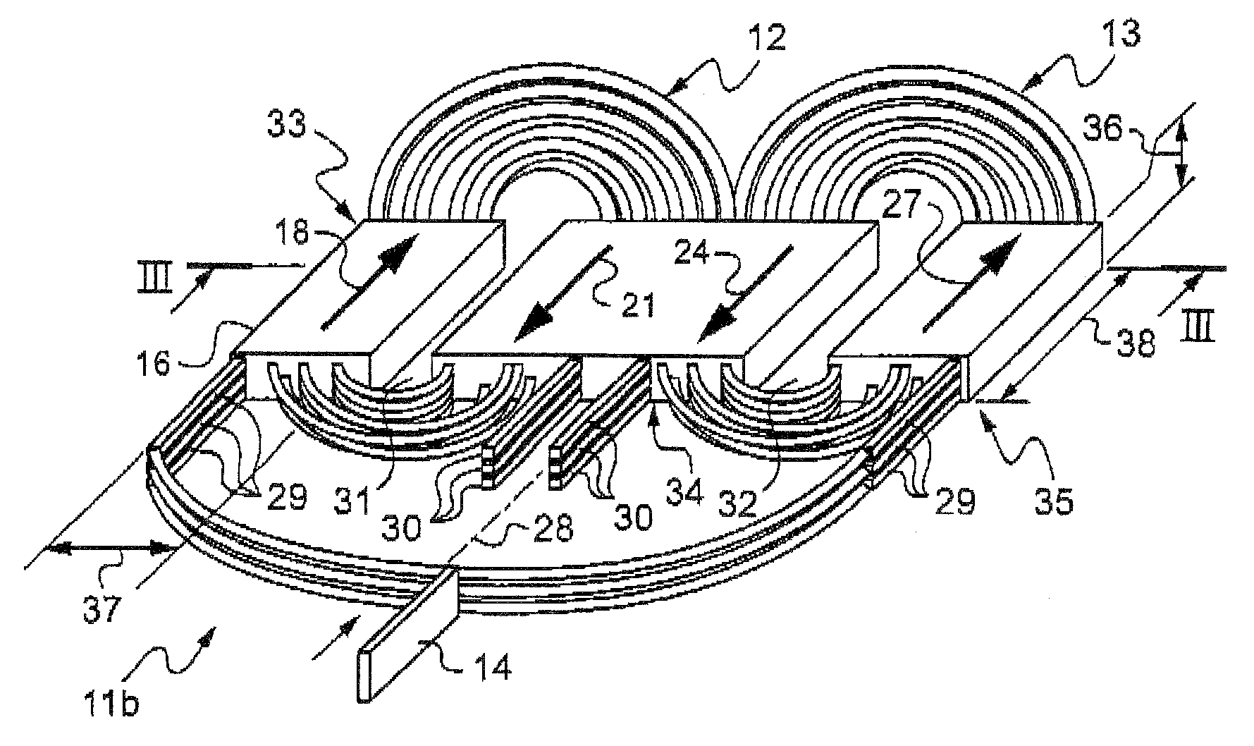
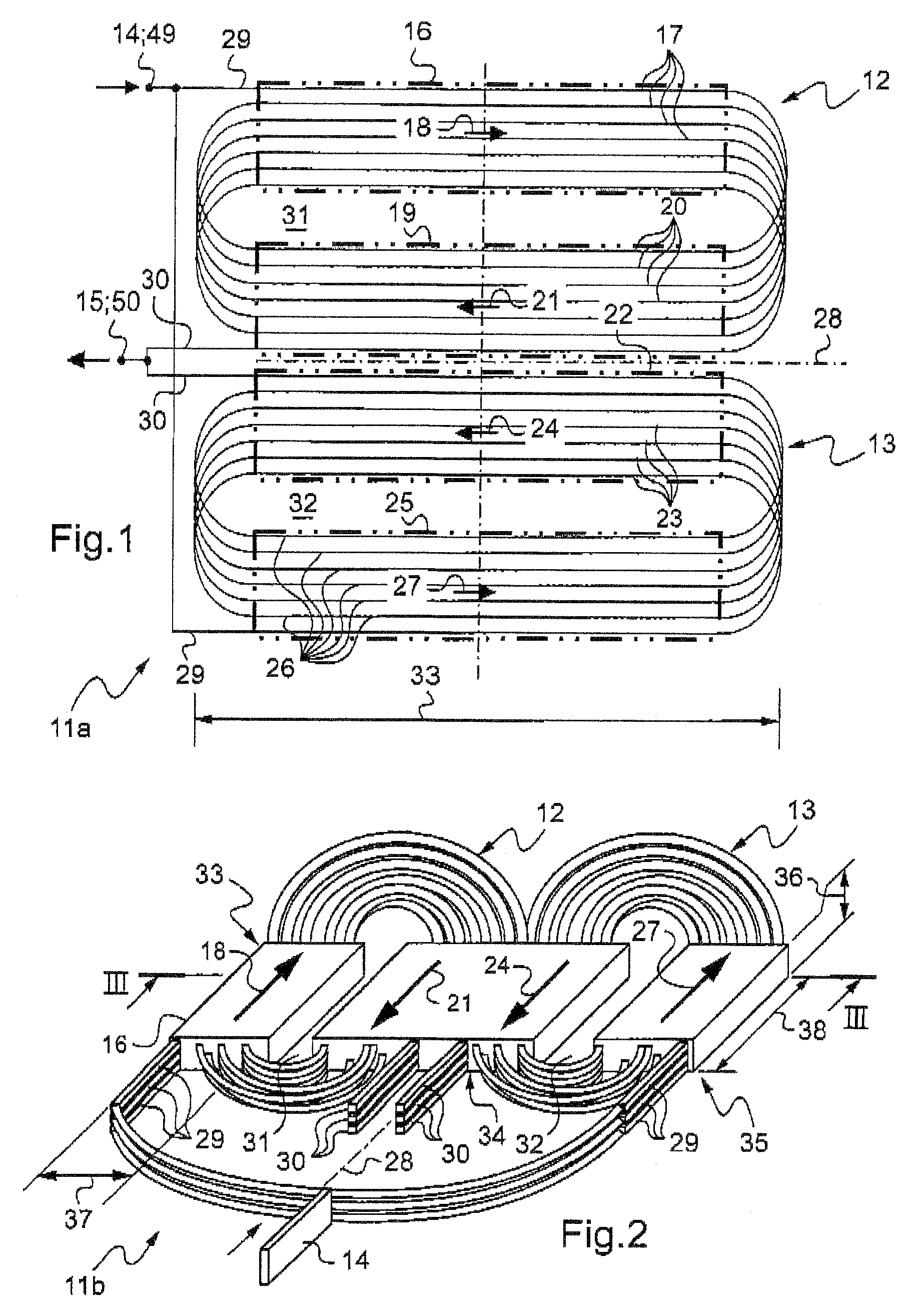
[0035]In accordance with an aspect of the invention, the system for de-icing the blades of a helicopter by induction comprises inductors embedded in the blade that, once subjected to alternating-current at high-frequency, emit a magnetic field from the center of the blade towards the outside. The magnetic field then induces currents in the metal cover protecting the leading edge (which cover is made of an electrically-conductive material).

[0036]By subjecting the electrically-conductive material covering the leading edge to a varying magnetic field, the variation in the magnetic flux induces electromotive forces within the material (Lentz's law) that give rise to induced currents (eddy currents). The eddy currents then heat the material of the cover by the Joule effect.

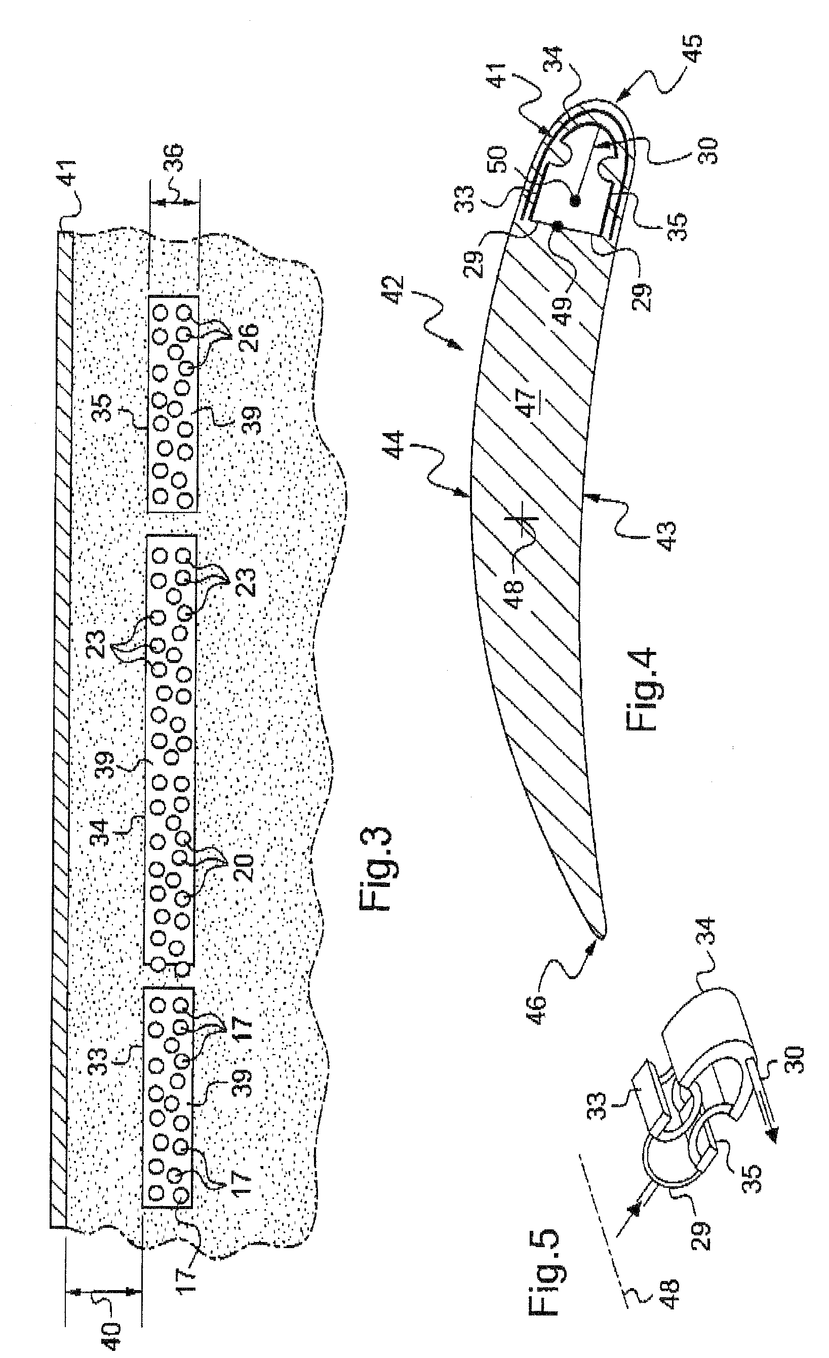
[0037]At high frequency, a harmful phenomenon known as the “skin” effect can disturb the distribution of current densities within the inductors: the currents within the material that is to be heated often penetrate onl...


PUM


Abstract

A device for de-icing an aircraft wall that comprises a composite structure (47) and layer (41) of electrically conductive material, which device comprises a plurality of thin inductor elements (33 to 35) designed to extend substantially parallel to the layer of conductive material at a distance therefrom that is small enough to ensure that when the inductor is powered by an AC source of appropriate frequency, the layer or skin heats rapidly and uniformly, without significantly heating the composite structure.

Description

[0001]The present invention relates to a method and a device for de-icing an aircraft wall.[0002]The technical field of the invention is that manufacturing helicopters.BACKGROUND OF THE INVENTION[0003]The present invention relates more particularly to a method and a device for heating the outside face of a wall of a rotorcraft in order to avoid ice forming and / or accumulating on the said face, and to a rotorcraft wall—in particular a blade of a lift and propulsion rotor—fitted with such a device.[0004]It is well-known that ice forming and accumulating on an outside surface of an aircraft can rapidly modify the aerodynamic characteristics of said surface; in particular when said surface is a rotary wing of a rotorcraft, such icing can cause the rotorcraft to crash.[0005]A large amount of research has been undertaken to prevent or combat the formation of ice.[0006]In U.S. Pat. No. 4,060,212 and FR-2 346 217, proposals are made for a de-icing device using microwaves; in U.S. Pat. No. 4...

Claims


Application Information

Patent Timeline
Patent Type & Authority Applications(United States)
IPC IPC(8): B64D15/12F01D5/08
CPCB64D15/12H05B6/02H05B6/105H05B6/36
Inventor BOSCHET, PATRICKLORCET, BRUNO
Owner EUROCOPTER
Why Eureka
Try Eureka