Electrode for supercapacitor having metal oxide deposited on ultrafine carbon fiber and the fabrication method thereof

Active Publication Date: 2008-10-16
KOREA INST OF SCI & TECH
View PDF2 Cites 41 Cited by
  • Summary
  • Abstract
  • Description
  • Claims
  • Application Information

AI Technical Summary

Benefits of technology

[0008]The present invention provides an electrode for a supercapacitor which can maintain a high specific capacitance during high-speed charging and discharging cycles, which compris

Problems solved by technology

However, ruthenium is expensive and only the ruthenium oxide exposed on the surface

Method used


Image

  • Electrode for supercapacitor having metal oxide deposited on ultrafine carbon fiber and the fabrication method thereof
  • Electrode for supercapacitor having metal oxide deposited on ultrafine carbon fiber and the fabrication method thereof
  • Electrode for supercapacitor having metal oxide deposited on ultrafine carbon fiber and the fabrication method thereof

Examples


example 1

Electrode Comprising Ruthenium Oxide Deposited on a Carbon Substrate Containing Ground Graphitical Ultrafine Carbon Fibers

1. Preparation of a Carbon Substrate

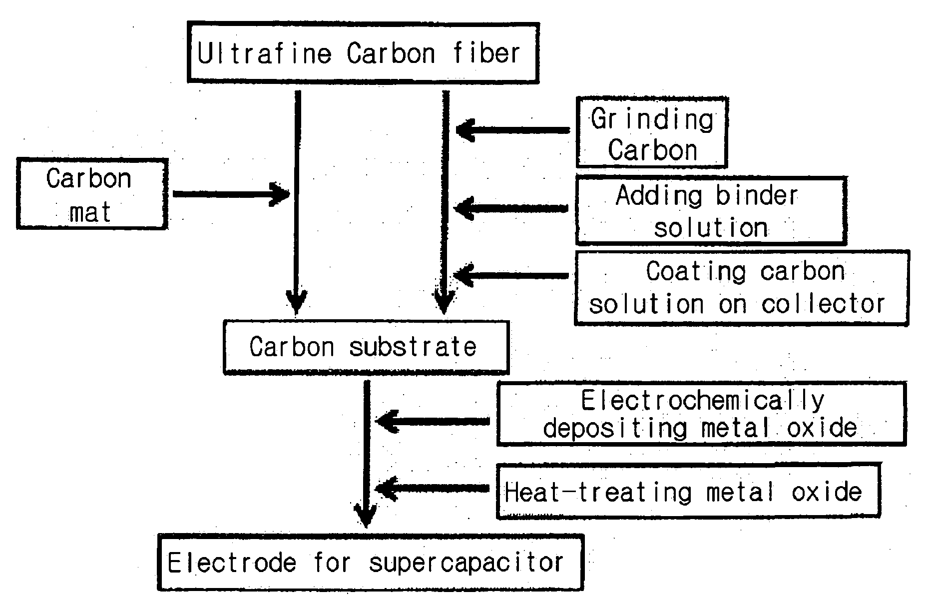
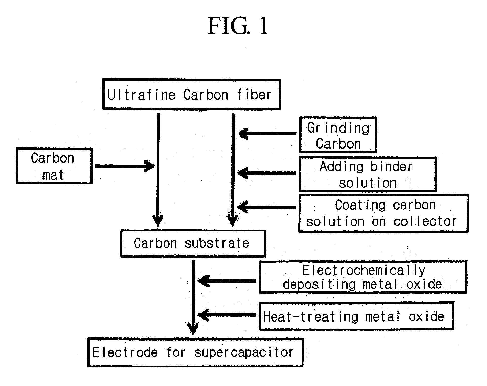
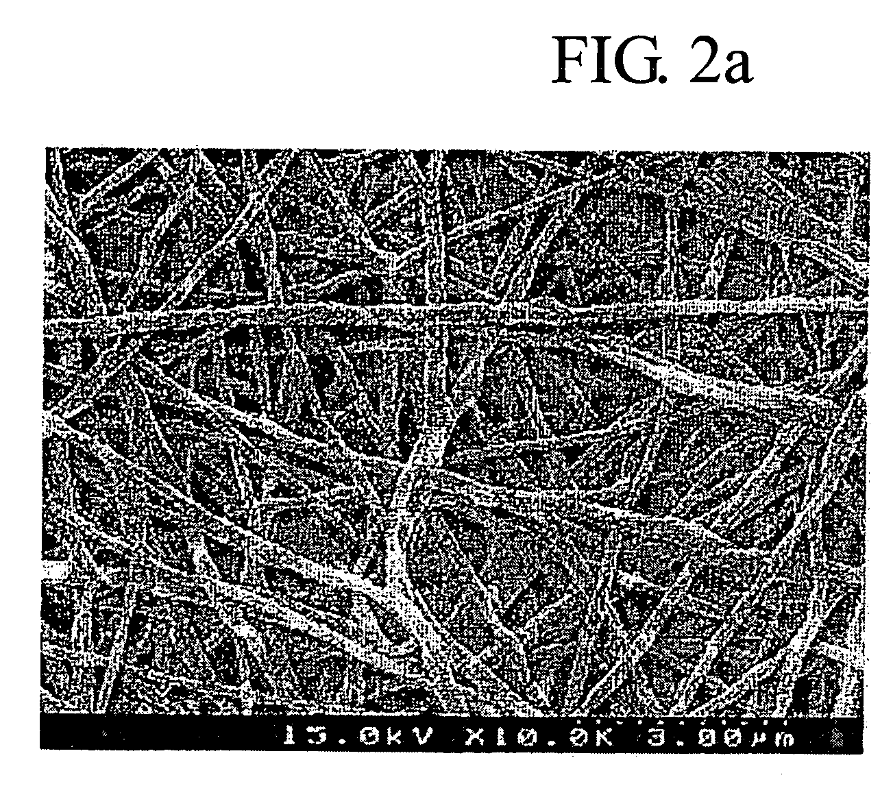
[0056]0.85 g of a graphitical ultrafine carbon fiber having a specific surface area of 430 m2 / g was mixed with 0.05 g of Super-P. Added to the resulting mixture was the polymer solution containing 0.1 g of PVdF-HFP dissolved in 5 ml of NMP. The resulting mixture was coated on a titanium collector using the doctor-blade method to obtain a carbon substrate. As shown in FIG. 2b, the graphitical carbon fibers having an average diameter of 100 to 200 nm were well mixed with Super-P and PVdF-HFP.

2. Deposition of RuO2

[0057]The deposition of a ruthenium oxide thin layer on the carbon substrate was carried out by cyclic voltammetry method using an aqueous solution of ruthenium chloride. The graphitical carbon fiber substrate was soaked in 0.05M ruthenium chloride, and the deposition was carried out by sweeping 10 times at a voltage of ...

example 2

Electrode Comprising Ruthenium Oxide Deposited on Graphitical Ultrafine Carbon Fibers Having Carbon Nanofibers Grown Thereon

[0060]An electrode was prepared in the same way as described in Example 1 by employing ultrafine carbon fibers which have carbon nanofibers or carbon nanotubes grown on the surface of the graphitical ultrafine carbon fibers. Added to a polymer solution containing 0.1 g of PVdF-HFP dissolved in 5 ml of NMP were 0.85 g of the ultrafine carbon fibers which have carbon nanofibers grown on the surface and 0.05 g of Super-P. The resulting mixture was coated on a titanium collector using the doctor-blade method to obtain a carbon substrate.

[0061]To the resulting carbon substrate, a ruthenium oxide was deposited in the same way as described in Example 1.

[0062]The electrode was tested as an electrode for a supercapacitor, and the results were similar to that of Example 1.

example 3

Electrode Comprising Ruthenium Oxide Deposited on a Carbon Mat Substrate Made of Graphitical Ultrafine Carbon Fibers

[0063]A carbon substrate was prepared in the same way as described in Example 1, except that a carbon mat was attached to a collector without grinding.

[0064]A carbon substrate was prepared by dipping a carbon mat in a polymer solution containing 0.5 g of PVdF-HFP dissolved in 10 ml of NMP, and the resulting carbon mat was attached to the surface of a collector to obtain an electrode.

[0065]The test results were similar to those of Example 1, except that the specific capacitance of the electrode slightly decreased due to the increase of resistance caused by a binder.


PUM

PropertyMeasurementUnit
Temperatureaaaaaaaaaa
Thicknessaaaaaaaaaa
Diameteraaaaaaaaaa

Abstract

The present invention discloses an improved electrode for a supercapacitor and a method of preparation thereof. The inventive electrode comprises a collector, a carbon substrate disposed on the collector comprising ultrafine carbon fibers having a specific surface area of at least 200 m2/g (BET) and a d002 value of 0.36 nm or less, and a metal oxide thin layer formed on the carbon substrate. The electrode of the subject invention retains a high specific capacitance during high-speed charging and discharging cycles.

Description

FIELD OF THE INVENTION[0001]The present invention provides an electrode for a supercapacitor comprising an electrochemically deposited metal oxide thin layer on ultrafine carbon fibers having a high specific surface area and a high electric conductivity, and the fabrication method thereof.BACKGROUND OF THE INVENTION[0002]A supercapacitor can be broadly classified as an electric double layer capacitor (EDLC) which employs carbon particles or fibers having a high specific surface area as an electrode material or as a pseudocapacitor comprising a metal oxide or a conductive polymer.[0003]An EDLC exhibits a long lifetime but due to the accumulation of charges only on the surface of the electric double layer, the capacitance thereof is lower than that of a metal oxide-based or an electric conductive polymer-based supercapacitor.[0004]The metal of a metal oxide-based supercapacitor is capable of undergoing a change in its multiple valence states, which allows oxidation and reduction react...

Claims


Application Information

Patent Timeline
IPC IPC(8): B29C47/00H01G9/00B82Y99/00H01G11/02H01G11/22H01G11/24H01G11/34H01G11/36H01G11/40H01G11/44H01G11/46H01G11/86
CPCB82Y30/00B82Y40/00C01B31/0253D01F9/20H01G11/34H01G11/36H01G11/46H01G11/86Y02E60/13Y02T10/7022H01G11/24H01G11/28C01B32/168Y02T10/70
Inventor KIM, DONG YOUNGJO, SEONG MUJANG, SUNG-YEONAHN, YOUNG RACK
Owner KOREA INST OF SCI & TECH
Why Eureka
Try Eureka