
Target Substance Sensor and Method Thereof Using a Photonic Crystal

a target substance and photonic crystal technology, applied in the direction of optical radiation measurement, instruments, spectrometry/spectrophotometry/monochromators, etc., can solve the problems of reducing the sensitivity and failing to make accurate density measurement, and achieve high-sensitivity density detection, enhance the effect of the drop efficiency of the electromagnetic wave and accurate measurement in compensation

Inactive Publication Date: 2008-10-16
PANASONIC CORP
View PDF10 Cites 17 Cited by
  • Summary
  • Abstract
  • Description
  • Claims
  • Application Information

AI Technical Summary

Benefits of technology

"The present invention provides a target substance sensor that is highly sensitive and compact. The sensor includes a photonic crystal with a sensing resonator and a detector. The sensing resonator has a photonic crystal structure that resonates at a specific wavelength when exposed to the target substance, resulting in a variation in the intensity of the electromagnetic wave emitted from the resonator. The detector receives the emitted wave and issues a signal indicative of its intensity. The sensor is designed to be highly sensitive to the target substance and can detect its density. The invention provides a solution for detecting target substances in a cost-effective and efficient manner."

Problems solved by technology

However, when the cyclic structure of refractive index distorts, the group velocity goes out of the intended value at the distorted portion, which fails to make accurate density measurement.
Further, since the three dimensional photonic crystal has a relatively large thickness, the propagation mode becomes multi-modes including the slower group velocity mode and higher group velocity mode, which may lower the sensitivity than with the constant group velocity.

Method used


Image

  • Target Substance Sensor and Method Thereof Using a Photonic Crystal
  • Target Substance Sensor and Method Thereof Using a Photonic Crystal
  • Target Substance Sensor and Method Thereof Using a Photonic Crystal

Examples


1st embodiment

[0064]In the present embodiment, the electromagnetic wave of the specific wavelength that the target substance absorbs is caused to resonate at the resonator so as to detect the target substance based upon an attenuation factor of the output from the resonator. The applicable target substance includes that has a prominent character of absorbing the electromagnetic wave of the specific wavelength, for example, carbonic acid gas and nitrogen gas, and the like gas.

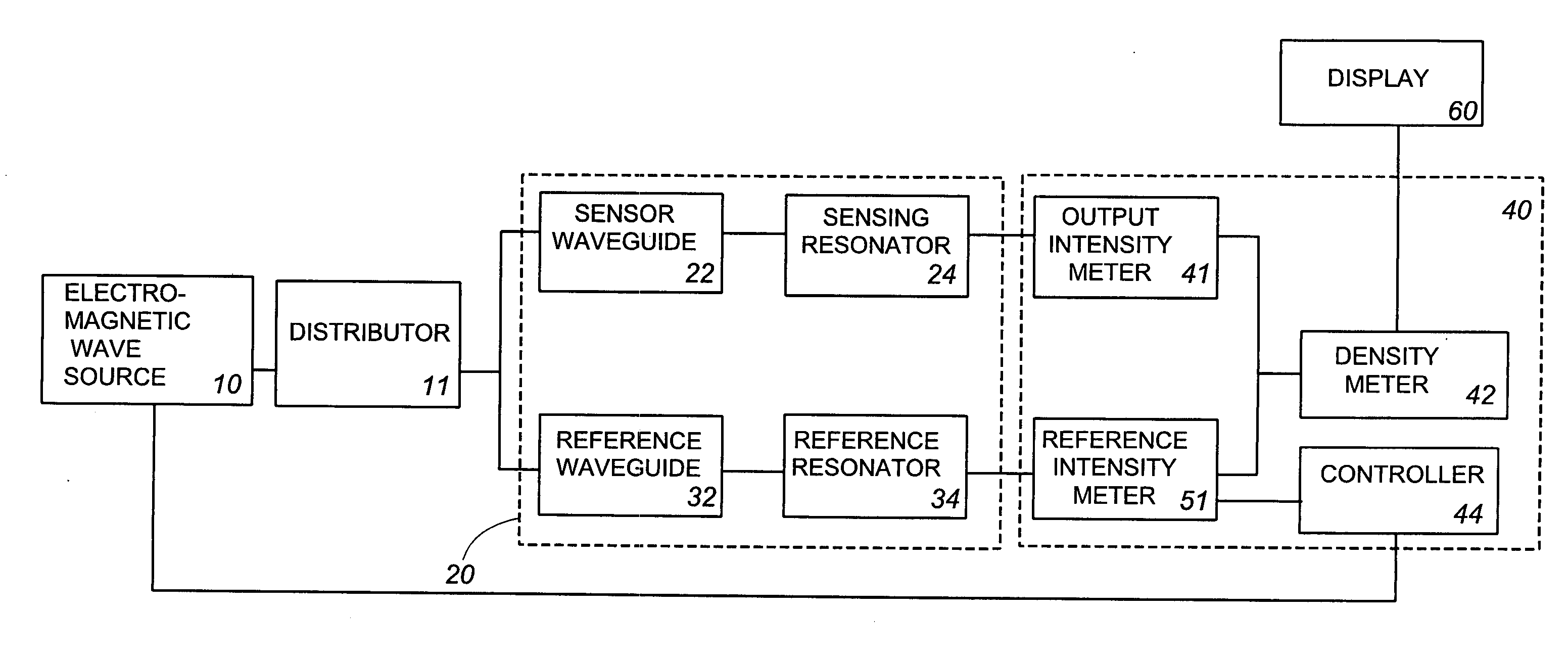
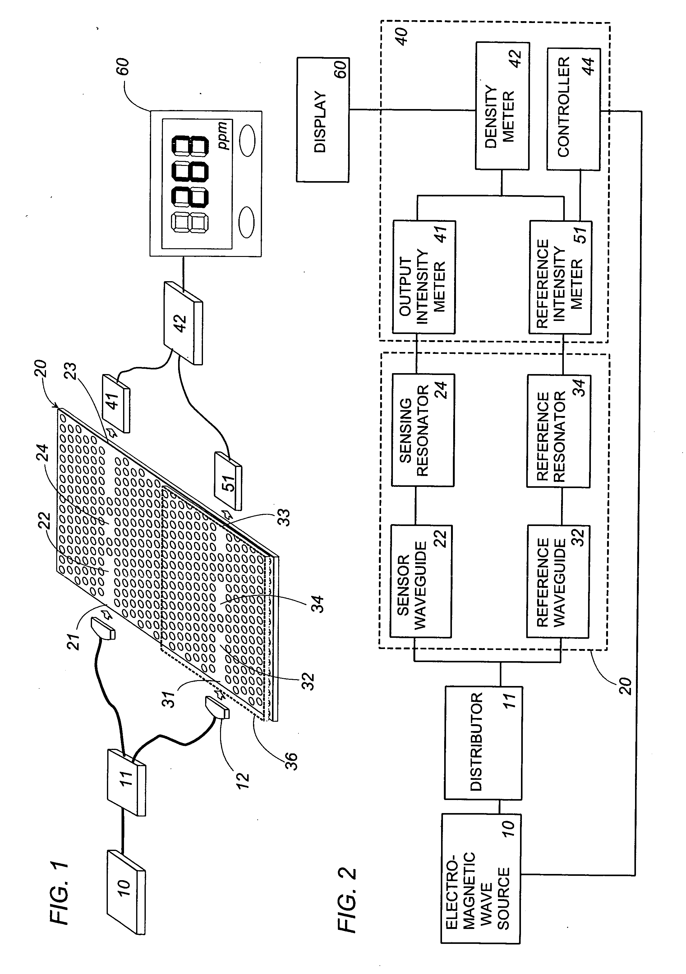
[0065]FIGS. 1 and 2 illustrates the sensor in accordance with the present embodiment in which the photonic sensor element 20 is formed with a senor waveguide 22 and a reference waveguide 32 which introduce the electromagnetic waves including that having the specific wavelength, for example, an infrared ray having a wavelength of 2 μm to 13 μm, as well as a sensing resonator 24 and a reference resonator 34 which are electromagnetically coupled respectively to the waveguides. The resonators are each configured to resonate the e...

2nd embodiment

[0079]FIG. 9 illustrates a second embodiment of the present invention in which the photonic sensor element 20 is configured to supply the electromagnetic wave from the source 10 to the sensing resonator 24 and the reference resonator 34 through a single input port 21. The photonic sensor element 20 is formed with a first photonic crystalline structure PC1 and a second photonic crystalline structure PC2 which are of different crystalline structures from each other. That is, the two different crystalline structures have minute circular pores of altering the refractive index which are arranged at different cycles within the two-dimensional array to selectively propagate the electromagnetic wave of different wavelengths. The sensor waveguide includes an input waveguide 22A extending over the two crystalline structures PC1 and PC2, and two output waveguides 22B1 and 22B2 belonging to each of the crystalline structures. The sensing resonator 24 and the reference resonator 34 are respectiv...

3rd embodiment

[0081]FIGS. 10 and 11 illustrates an embodiment discloses a scheme realized for measurement of the target substance which has a prominent character of altering the refractive index of the atmosphere. The target substance includes, for example, a steam and alcohol. The density measurement of the target substance is made by making the use of the phenomenon that the wavelength that resonates at the sensing resonator will shift in response to the alternation of the refractive index around the sensing resonator caused by the presence of the target substance. FIG. 12 indicates a relation between the refractive index of the target substance and the corresponding wavelength of the electromagnetic wave resonating at the resonator. Thus, by designing the sensing resonator to resonate at the specific wavelength determined by the target substance, the density of the target substance can be regarded as a function of the output intensity emitted from the sensing electrode 24.

[0082]For this purpos...


PUM

PropertyMeasurementUnit
thicknessaaaaaaaaaa
thicknessaaaaaaaaaa
refractive indexaaaaaaaaaa

Abstract

A highly sensitive and compactible target substance sensor for detection of the target substance using a photonic crystal and a method thereof are provided.The sensor of the present invention includes an electromagnetic wave source of supplying an electromagnetic wave, a photonic sensor element, and a detector. The photonic sensor element has photonic crystalline structure and is configured to include a sensor waveguide for introducing the electromagnetic wave, and a sensing resonator electromagnetically coupled to the sensor waveguide for resonating the electromagnetic wave at specific wavelength. The sensing resonator is exposed to an atmosphere including the target substance so as to vary a characteristic of the electromagnetic wave emitted from the sensing resonator. The detector is configured to receive the electromagnetic wave emitted from the sensing resonator to recognize an intensity variation of the electromagnetic wave and issue a signal indicative of a characteristic of the target substance.

Description

TECHNICAL FIELD[0001]The present invention is directed to a sensor for detection of a target substance using a photonic crystal as well as a method thereof.BACKGROUND ART[0002]A prior art publication “Photonic Crystals” by R. Wehrspohn, ISBN3-527-40432-5, p. 238-246 discloses a sensor using a photonic crystal. The sensor uses a three-dimensional photonic crystal of bulk-type as a sensing element, and is configured to introduce a target gas through one of faces opposed with respect to the thickness of said sensing element, and to guide a light having a wavelength in match with an absorption wavelength of the target gas through the one face of the sensing element, thereby detecting the light emitted from the other face of the sensing element by use of a detector such as a photo-detector for calculating a gas density based upon the intensity of the detected light.[0003]Generally, a group velocity Vg of the electromagnetic wave propagating within the photonic crystal is defined by Vg=(d...

Claims


Application Information

Patent Timeline
Patent Type & Authority Applications(United States)
IPC IPC(8): G01N21/00G01N21/35G01N21/3504G01N21/45G01N21/77G02B6/122
CPCB82Y20/00G01N21/774G01N21/3504G01N2021/7776G02B6/1225G01N21/7746
Inventor NODA, SUSUMUASANO, TAKASHITAKANO, HITOMICHI
Owner PANASONIC CORP
Learn More