Turbocharger and Variable-Nozzle Cartridge Therefor

a variable-nozzle cartridge and turbocharger technology, which is applied in the direction of liquid fuel engines, machines/engines, fuel injecting pumps, etc., can solve the problems of relatively complex variable-nozzle mechanism and challenge in the assembly of the turbocharger, so as to reduce the cost and complexity of manufacturing, reduce the thermal stress, and reduce the thermal stress

Active Publication Date: 2008-10-23
GARRETT TRANSPORATION I INC
View PDF11 Cites 38 Cited by
  • Summary
  • Abstract
  • Description
  • Claims
  • Application Information

AI Technical Summary

Benefits of technology

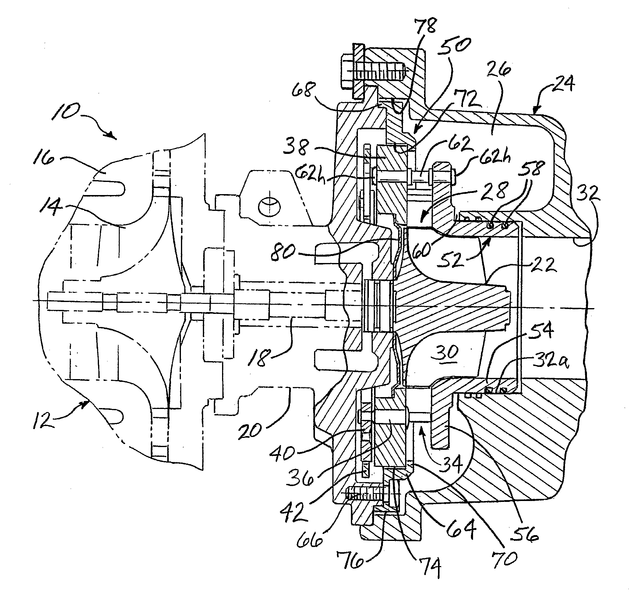
[0010]The cartridge is installable into the turbocharger and removable therefrom as a unit, which aids in the process of assembling the turbocharger. The mechanical and thermal decoupling of the retainer ring from the insert helps reduce the thermal stresses to which the cartridge is subjected as a result of the large temperature gradient between the turbine housing and the center housing. More particularly, the retainer ring is in thermal communication with the relatively low-temperature center housing, while the insert is in thermal communication with the relatively high-temperature turbine housing. The decoupling of the retainer ring from the insert reduces the thermal stresses to which these parts are subjected. Additionally, the cost and complexity of manufacturing are reduced by making these parts as separate members.
[0011]Preferably, the turbine housing is fastened to the center housing in such a manner that a gap is defined between the turbine housing and the retainer ring. This gap provides decoupling between the turbine housing and the retainer ring, which helps to reduce stresses that could otherwise be imposed on the cartridge as a result of differential thermal deformation between the turbine housing and cartridge.

Problems solved by technology

One of the challenges in boosting engine performance with a turbocharger is achieving a desired amount of engine power output throughout the entire operating range of the engine.
The variable vane mechanism is relatively complicated and thus presents a challenge in terms of assembly of the turbocharger.

Method used


Image

  • Turbocharger and Variable-Nozzle Cartridge Therefor
  • Turbocharger and Variable-Nozzle Cartridge Therefor

Examples


Embodiment Construction

[0019]The present inventions now will be described more fully hereinafter with reference to the accompanying drawings, in which some but not all embodiments of the inventions are shown. Indeed, these inventions may be embodied in many different forms and should not be construed as limited to the embodiments set forth herein; rather, these embodiments are provided so that this disclosure will satisfy applicable legal requirements. Like numbers refer to like elements throughout.

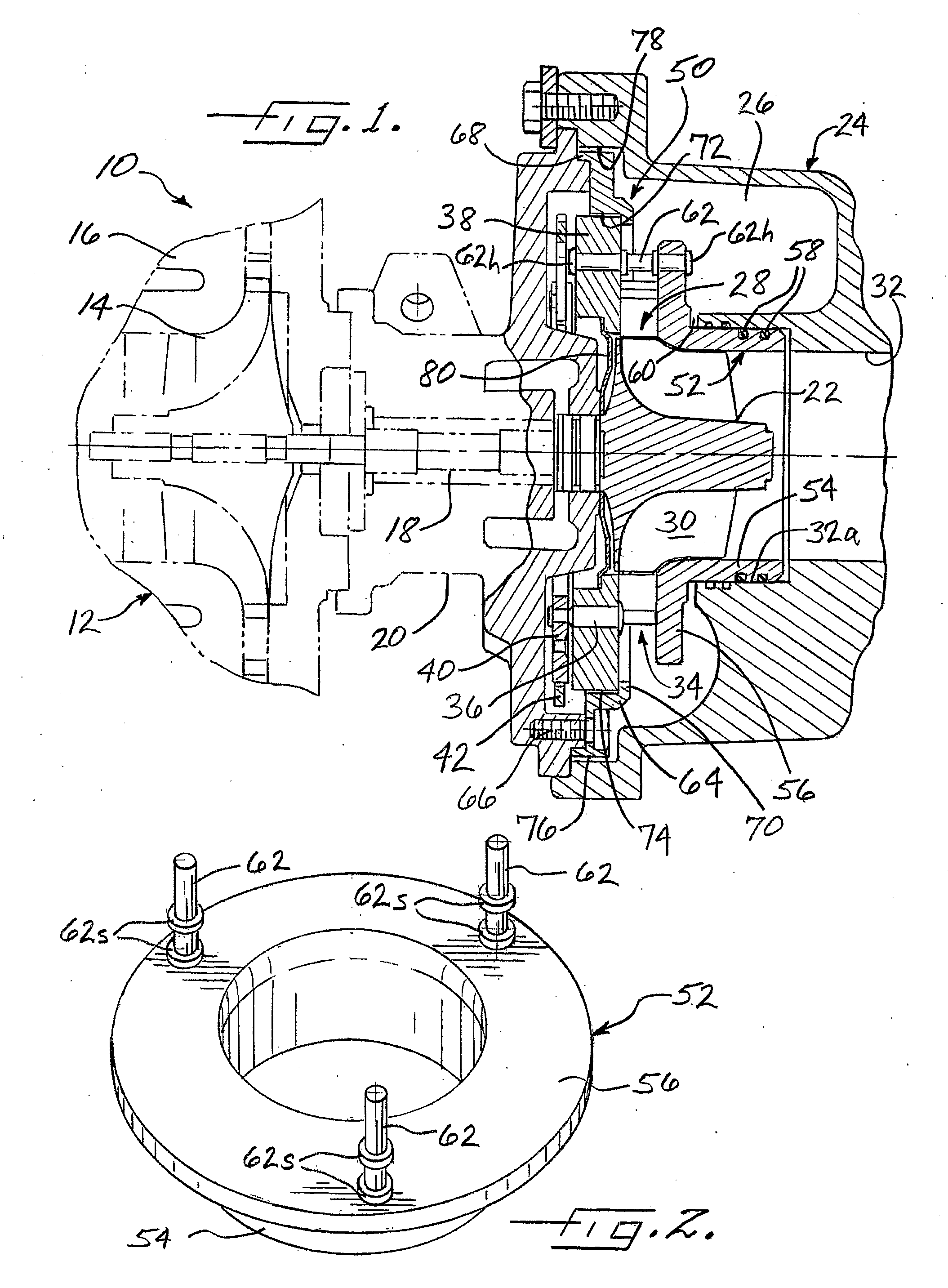
[0020]A turbocharger 10 in accordance with one embodiment of the invention is illustrated in fragmentary perspective view in FIG. 1. The turbocharger comprises a compressor 12 having a compressor wheel or impeller 14 mounted in a compressor housing 16 on one end of a rotatable shaft 18. The shaft is supported in bearings (not specifically illustrated) mounted in a center housing 20 of the turbocharger. The shaft 18 is rotated by a turbine wheel 22 mounted on the other end of the shaft 18 from the compressor whe...


PUM


Abstract

A variable-nozzle turbocharger includes a cartridge containing a variable vane mechanism connected between the center housing and the turbine housing. The cartridge comprises an annular nozzle ring supporting an array of rotatable vanes, an insert having a tubular portion sealingly received into the bore of the turbine housing and having a nozzle portion extending radially out from one end of the tubular portion and being axially spaced from the nozzle ring with the vanes therebetween, a plurality of spacers connected between the nozzle portion of the insert and the nozzle ring, and an annular retainer ring fastened to the center housing so as to capture the nozzle ring between the retainer ring and the center housing. The retainer ring is formed as a separate part from the insert ring and is mechanically and thermally decoupled from the insert.

Description

BACKGROUND OF THE INVENTION[0001]The present invention relates to turbochargers having a variable-nozzle turbine in which an array of movable vanes is disposed in the nozzle of the turbine for regulating exhaust gas flow into the turbine.[0002]An exhaust gas-driven turbocharger is a device used in conjunction with an internal combustion engine for increasing the power output of the engine by compressing the air that is delivered to the air intake of the engine to be mixed with fuel and burned in the engine. A turbocharger comprises a compressor wheel mounted on one end of a shaft in a compressor housing and a turbine wheel mounted on the other end of the shaft in a turbine housing. Typically the turbine housing is formed separately from the compressor housing, and there is yet another center housing connected between the turbine and compressor housings for containing bearings for the shaft. The turbine housing defines a generally annular chamber that surrounds the turbine wheel and ...

Claims


Application Information

Patent Timeline
Patent Type & Authority Applications(United States)
IPC IPC(8): F02B37/24F01D17/16
CPCF01D17/165F02M59/105F02M63/0047F05D2220/40
Inventor HETTINGER, RAPHAELCASTAN, JOELPERRIN, JEAN-LUCSAUSSE, LORRAIN
Owner GARRETT TRANSPORATION I INC
Why Eureka
Try Eureka