
Advanced Metal-Air Battery Having a Ceramic Membrane Electrolyte Background of the Invention

Active Publication Date: 2008-10-30
FIELD UPGRADING USA INC
View PDF87 Cites 165 Cited by
  • Summary
  • Abstract
  • Description
  • Claims
  • Application Information

AI Technical Summary

Benefits of technology

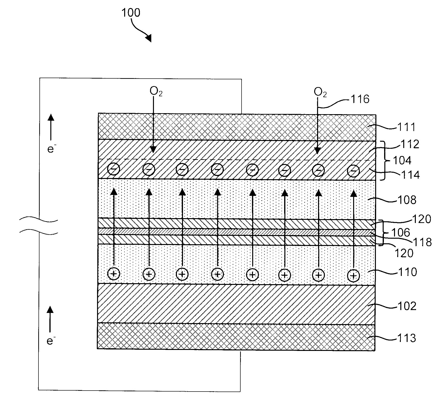
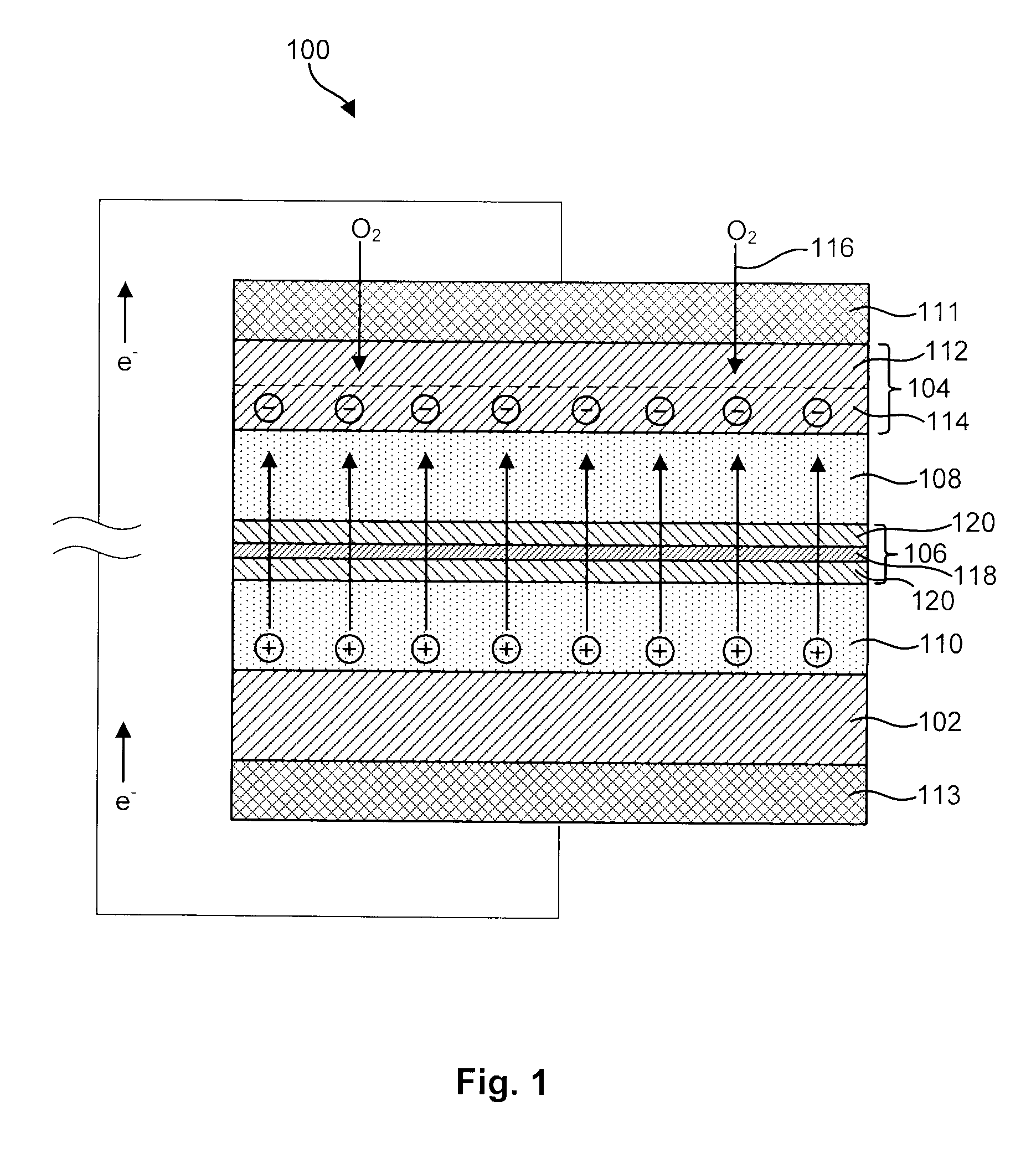
[0014]In certain embodiments, the ion-selective membrane may include a monolith of dense layer, a dense layer sandwiched between porous layers. The dense layer may be fabricated from an ionically conductive material, such as LiSICON, NaSICON, or other suitable ceramic appropriate to the anode material that is also impermeable to the aqueous catholyte. The porous layers, in selected embodiments, may provide structural integrity and rigidity to the dense layer. In certain embodiments, these porous layers may be infiltrated with the anolyte and catholyte, respectively, in order to provide ionic conductivity between the dense layer, and the anolyte and catholyte, respectively.
[0015]In selected embodiments, the cathode may be a multi-layer structure. For example, in certain embodiments, the cathode may include a gas-diffusion layer that is hydrophobic but is permeable to oxygen. This may allow oxygen to enter the battery while preventing the aqueous catholyte from leaking out of the battery. A reaction layer may be placed adjacent to the gas-diffusion layer to reduce the oxygen molecules passing through the gas-diffusion layer. In selected embodiments, the reaction layer may contain or be infiltrated with a catalyst to aid in reducing the oxygen. In certain embodiments, this catalyst may include a perovskite-type compound. In other embodiments, this catalyst may include a manganese, cobalt and oxides thereof. In other embodiments, the reaction layer may also include an oxygen evolution catalyst to make the battery rechargeable.

Problems solved by technology

Nevertheless, conventional lithium-air batteries, like many other battery technologies, are hindered by various limitations.
The reaction products (i.e., lithium hydroxide, lithium peroxide, etc.) tend to clog up the pores of the cathode and limit the movement of reactants, significantly limiting the life of the battery.

Method used


Image

  • Advanced Metal-Air Battery Having a Ceramic Membrane Electrolyte Background of the Invention
  • Advanced Metal-Air Battery Having a Ceramic Membrane Electrolyte Background of the Invention
  • Advanced Metal-Air Battery Having a Ceramic Membrane Electrolyte Background of the Invention

Examples


Embodiment Construction

[0029]It will be readily understood that the components of the present invention, as generally described and illustrated in the Figures herein, could be arranged and designed in a wide variety of different configurations. Thus, the following more detailed description of the embodiments of the invention, as represented in the Figures, is not intended to limit the scope of the invention, as claimed, but is merely representative of certain examples of presently contemplated embodiments in accordance with the invention. The presently described embodiments will be best understood by reference to the drawings, wherein like parts are designated by like numerals throughout.

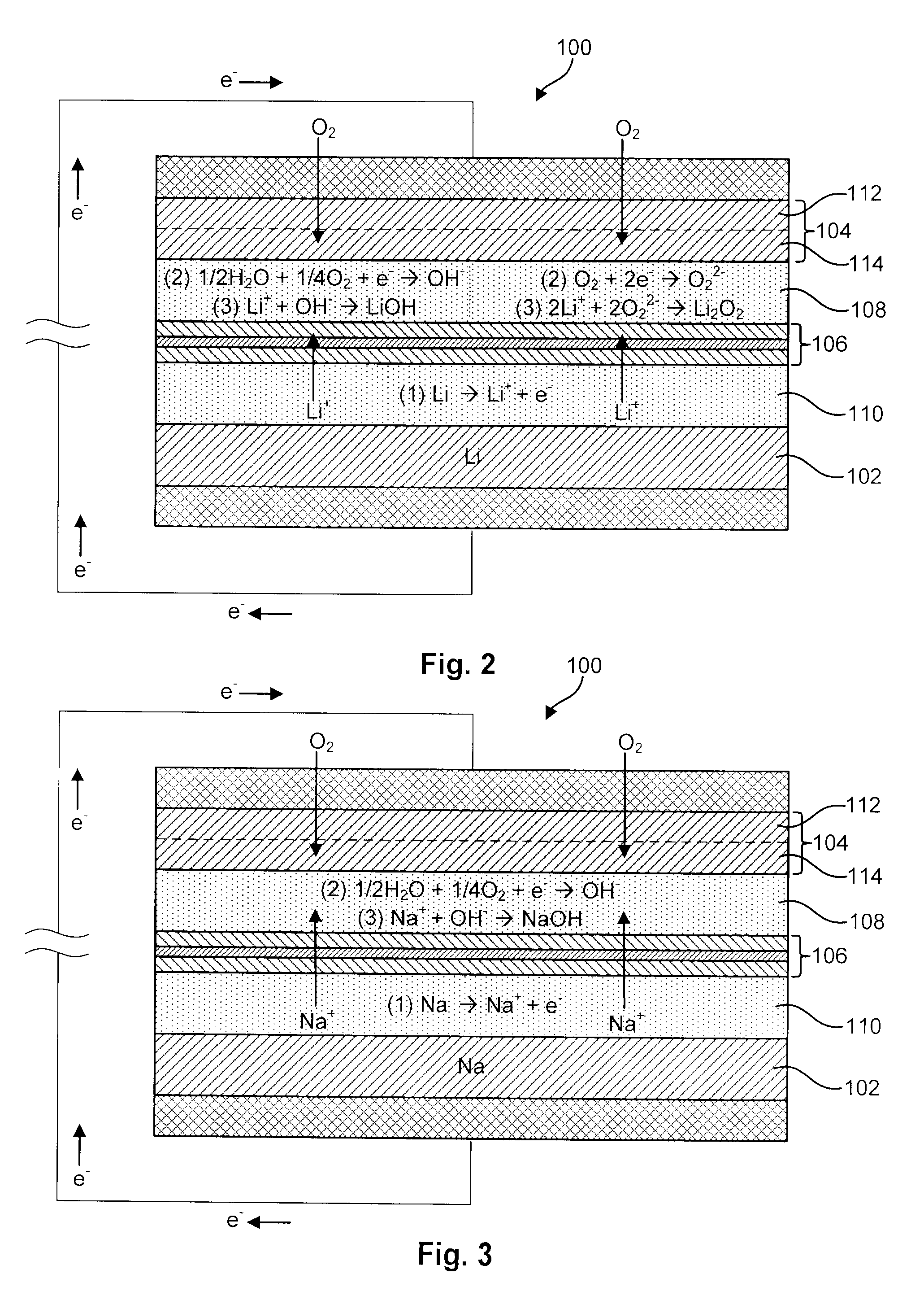
[0030]Referring to FIG. 1, in general, a metal-air battery 100 in accordance with the invention that overcomes various problems of the prior art may include an anode 102, a cathode 104, an electrolyte separator / membrane 106, and an aqueous catholyte layer 108 interposed between the electrolyte membrane 106 and the cathode...


PUM


Abstract

A metal-air battery is disclosed in one embodiment of the invention as including a cathode to reduce oxygen molecules and an alkali-metal-containing anode to oxidize the alkali metal (e.g., Li, Na, and K) contained therein to produce alkali-metal ions. An aqueous catholyte is placed in ionic communication with the cathode to store reaction products generated by reacting the alkali-metal ions with the oxygen containing anions. These reaction products are stored as solutes dissolved in the aqueous catholyte. An ion-selective membrane is interposed between the alkali-metal containing anode and the aqueous catholyte. The ion-selective membrane is designed to be conductive to the alkali-metal ions while being impermeable to the aqueous catholyte.

Description

RELATED APPLICATIONS[0001]This application claims the benefit of to U.S. Provisional Patent No. 60 / 829,499 filed on Oct. 13, 2006 and entitled ADVANCED LITHIUM BATTERIES BASED ON CERAMIC MEMBRANE ELECTROLYTE.U.S. GOVERNMENT INTEREST[0002]This invention was made with government support under Contract No. W91 QX-06-C-0092 awarded by the U.S. Army. This invention was also made with government support under Contract No. W9QX-06-C-0058 awarded by the U.S. Army. The government has certain rights in the invention.FIELD OF THE INVENTION[0003]This invention relates to batteries and more particularly to apparatus and methods for improving the performance of metal-air batteries.DESCRIPTION OF THE RELATED ART[0004]Our society has come to rely on batteries to power a myriad of devices, including computers, cell phones, portable music players, lighting devices, as well as many other electronic components. Nevertheless, there is an ongoing need for further advances in battery technology. For examp...

Claims


Application Information

Patent Timeline
IPC IPC(8): H01M6/24H01M4/40H01M50/434
CPCH01M2/1646H01M2/1673H01M2/18H01M4/40H01M12/02H01M12/06H01M12/08H01M2300/0002H01M2300/0017H01M2300/0068H01M2300/0094Y02E60/10H01M50/46H01M50/434
Inventor GORDON, JOHN HOWARDBALAGOPAL, SHEKARBHAVARAJU, SAIWATKINS, JOHN JOSEPH
Owner FIELD UPGRADING USA INC
Learn More