Temperature Control of Reaction Vessel, System with Reaction Vessel, Software Product for System and Use of System

a technology of reaction vessel and temperature control, which is applied in the direction of lighting and heating apparatus, laboratory glassware, instruments, etc., can solve the problems of limiting the speed of reaction, requiring a significant amount of time for the temperature change of the block, and the reaction itself occurring very fas

Active Publication Date: 2008-10-30
UNIOGEN OY
View PDF16 Cites 16 Cited by
  • Summary
  • Abstract
  • Description
  • Claims
  • Application Information

AI Technical Summary

Benefits of technology

[0014]Characteristic for the system is that it further comprises a data processing unit with software for dedicated data reduction for said detecting and/or quantitating of said analyte or analytes and said data processing unit controls at least one temperature change of the reaction volume (4) from a preceding temperature to a target temperature according to the method of claim 1.
[0015

Problems solved by technology

However, a major drawback of this approach is that a significant amount of time is required for the block to change its temperature: once the target temperatures have been reached, the reaction itself occurs very fast.
Therefore, it is the thermal mass of the block that is limiting the speed of the reaction rather than the reaction itself.
However, the process is still rather slow due to the fact that it takes time for the metal block to change its temperature.
However, when glass capillaries are used, the maximum reaction volume is often so small that it starts to limit the analytical sensitivity of the application.
The fragility of glass capillaries is also a problem as they break very easily when handled.
In these applications, however, the reaction volumes are even smaller and thus analytical sensitivity is heavily compromised.
Also, one either has to reuse the same amplification channel for many samples, which introduces a serious risk of carry-over contamination between different samples or alternatively, the amplification vessels have to be of

Method used


Image

  • Temperature Control of Reaction Vessel, System with Reaction Vessel, Software Product for System and Use of System
  • Temperature Control of Reaction Vessel, System with Reaction Vessel, Software Product for System and Use of System
  • Temperature Control of Reaction Vessel, System with Reaction Vessel, Software Product for System and Use of System

Examples


example 1

Effect of Using Heat Blocks Hotter and Cooler than the Target Temperatures on The Rate of Temperature Increase and Decrease in the Reaction Vessel of the System

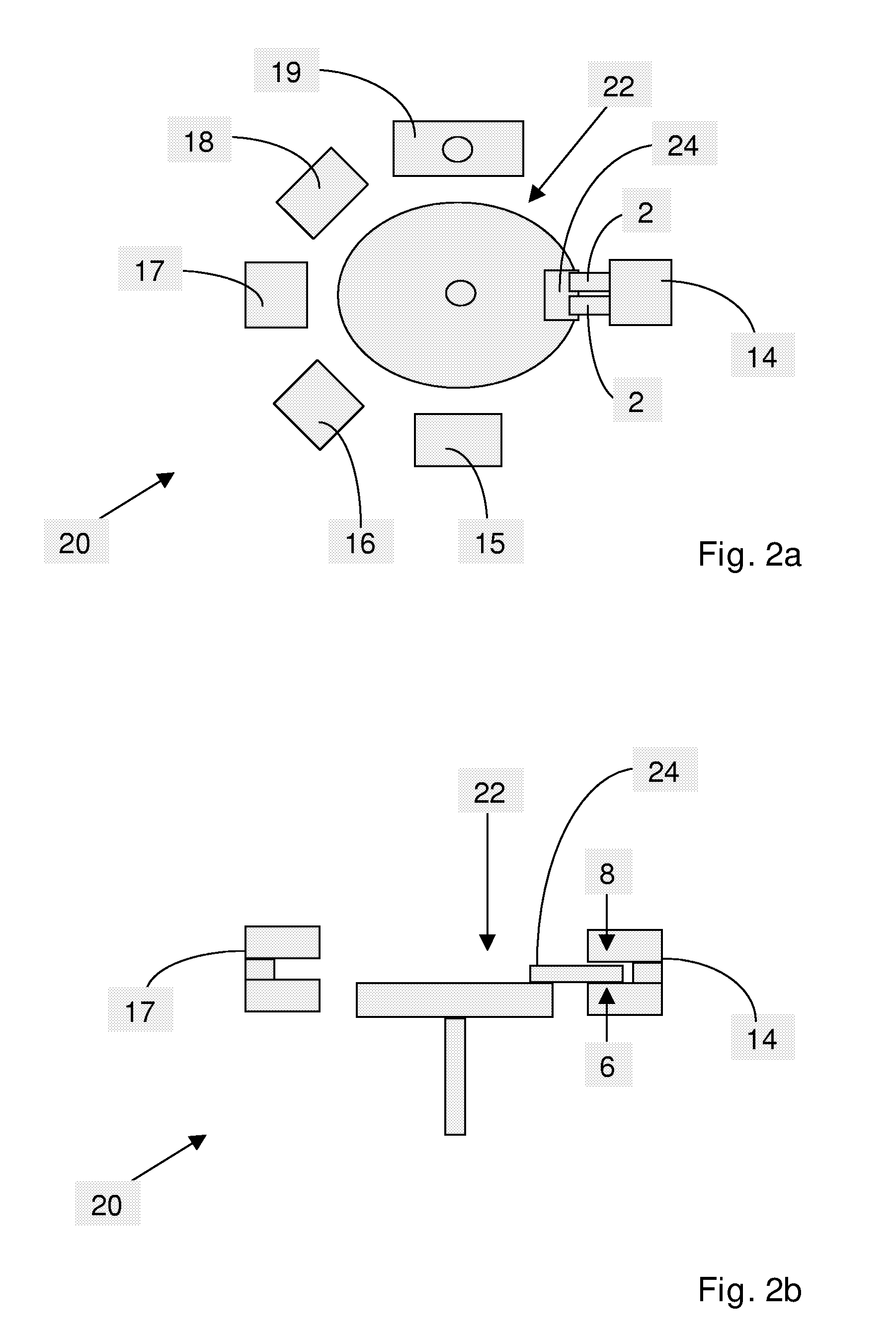
[0048]To optimize the speed of thermal cycling, a system according to the present invention was constructed that comprises several heat blocks maintained at predetermined temperatures. The blocks were maintained at 29° C. (the cold block); 61° C.; 97° C. and 115° C. A temperature sensor was placed inside a flat reaction vessel and the heating and cooling rates of the contents of the vessel were determined using two different methods of thermal cycling. In the first method, the reaction vessel was transferred from the block at 61° C. directly to the block at 97° C. and from the block at 97° C. directly back to the block at 61° C. The second method was performed according to the present invention so that to heat the contents of the reaction vessel from 61° C. to 97° C., the vessel was transferred from the block at 61° C. to the...

example 2

Effect of Using Aluminium Foil as a Material in the Reaction Vessel of the System on the Rate of Temperature Change Inside the Vessel

[0049]To determine the effect of using a metal foil instead of a plastic wall on one side of the reaction vessel, two identical polypropene vessel halves were laminated with either aluminium foil or a plastic foil. A temperature sensor was placed inside each vessel and the rates of temperature change were determined for both vessels using a system according to the present invention. This was done by changing the position of the vessel from a thermal block set at 105° C. to a block set at 27° C. for cooling or vice versa for heating. Separate temperature measurement data were recorded for cooling and heating the contents of the vessels. The data were fitted to a single exponential function and the half-lives of temperature change, i.e. the times required for the temperature inside the vessel to change to the half-point between 105° C. and 27° C., were d...

example 3

Use of the Method and System According to the Present Invention to Perform Real-Time Polymerase Chain Reaction

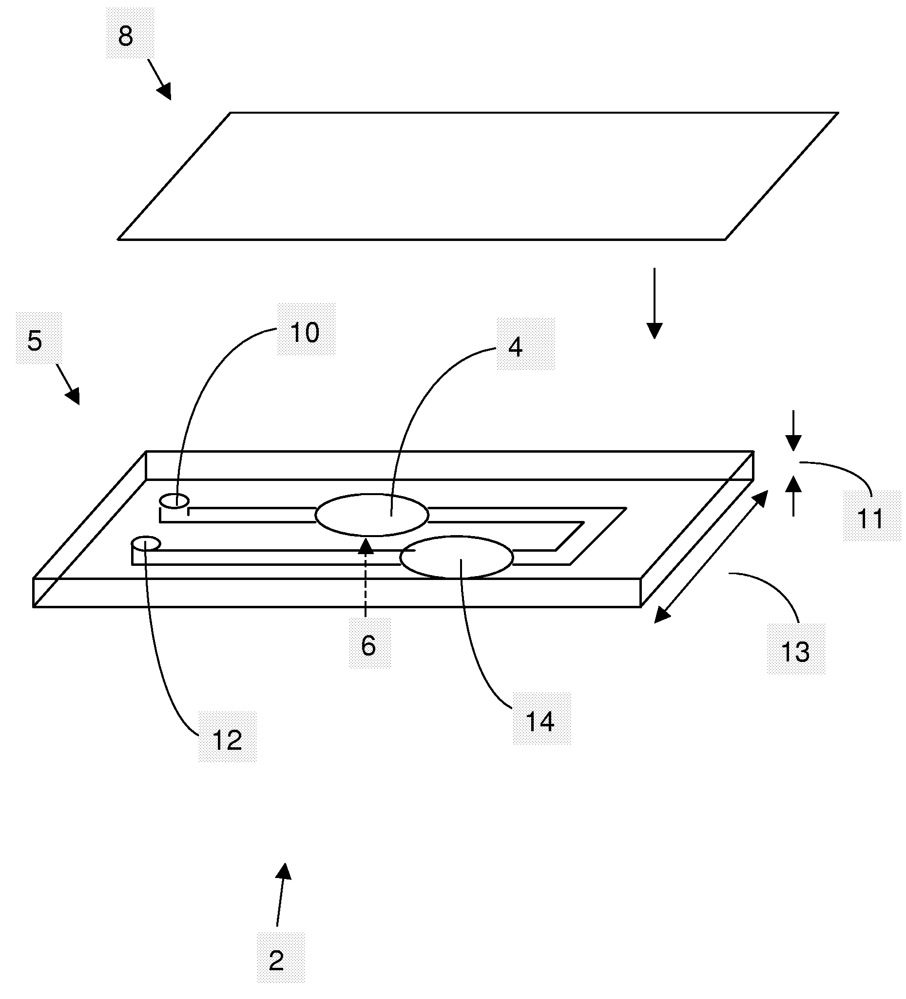
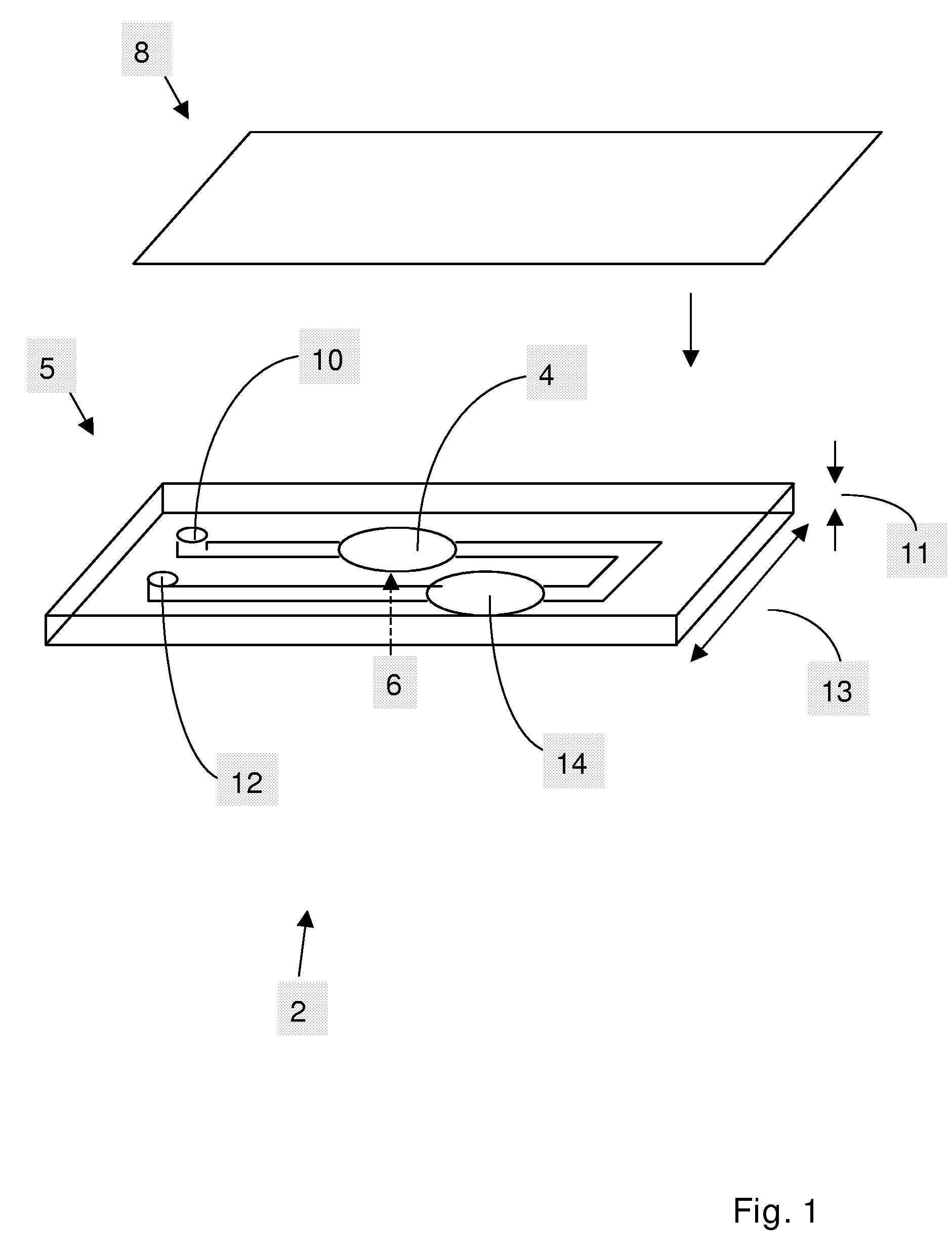
[0062]To demonstrate the applicability of the present invention to performing real-time polymerase chain reaction, a PCR assay was set up for bacteriophage T4. The assay chemistry was as described by Nurmi et al. (2002). The sequences of the oligonucleotides used in the assay were as follows: 5′ primer ATGTTCCACGCT-AAAAGACCTTATTGAAAA (SEQ ID NO: 1); 3′ primer CAGCAGAATGMCCG-MTCCACAAATAT (SEQ ID NO: 2); europium labelled probe ATTATTCATCAC-CGAGCGACTATTCMGATA (SEQ ID NO: 3) and QSY-7 labelled quencher probe GCTCGGTGATGAATMT (SEQ ID NO: 4). 30 μl amplification reactions consisted of 1× HotMaster Taq buffer (Eppendorf, Germany), 0.3 μM primers, 28 nM europium probe, 280 nM quencher probe, 2.5 mM magnesium chloride, 0.2 mM dNTPs and 1.25 U HotMaster Taq polymerase. The amplification reactions were carried out using the kind of a reaction vessel described in FIG. 1. For thermal cy...


PUM

PropertyMeasurementUnit
Poweraaaaaaaaaa
Poweraaaaaaaaaa
Volumeaaaaaaaaaa

Abstract

The invention relates to a method for rapid thermal control of a reaction volume (4) of a reaction vessel (2) for a change of temperature of the reaction volume (4) from a preceding temperature to a target temperature. Characteristic for the method is that the change of temperature is carried out by first bringing at least the second wall (8) of a second material with a high thermal conductivity of the reaction vessel (2) in direct contact with a first thermal block (14-19), at a temperature higher than the target temperature if the target temperature is higher than the preceding temperature, or correspondingly at a temperature lower than the target temperature if the target temperature is lower than the preceding temperature, for a time needed to bring the temperature of the reaction volume (4) to or close to the target temperature; and then bringing at least the second wall (8) in direct contact with a second thermal block (14-19) at the target temperature to bring the reaction volume (4) to the target temperature and/or keep the reaction volume (4) at the target temperature for the time intended. The first thermal block (14-19) is at a constant predetermined first temperature and the second thermal block (14-19) is at a constant predetermined second temperature. The invention also relates to a system (20) for detecting and/or quantitating a biological and/or chemical analyte or analytes in a sample supposedly containing said analyte or analytes for carrying out the method. The invention further relates to a software product for the system (20) and uses of the system (20).

Description

FIELD OF THE INVENTION[0001]The present invention relates to a method for rapid temperature control of a reaction vessel comprising a reaction volume for reacting of biological or chemical analytes to detect and / or quantitate said analytes in a sample containing said analytes. The present invention also relates to a system and software for the system for use in the method. The present invention further relates to the use of the system for detection of specific types of analytes.BACKGROUND OF THE INVENTION[0002]The publications and other materials used herein to illuminate the background of the invention, and in particular, cases to provide additional details respecting the practice, are incorporated by reference.[0003]The polymerase chain reaction (PCR; Saiki et al., 1985) is a good example of a chemical reaction that requires careful temperature control: in PCR, a specific DNA sequence is amplified by subjecting the DNA sample to cyclic temperature changes. First, the double strand...

Claims


Application Information

Patent Timeline
IPC IPC(8): C12Q1/68C12M1/02F28D15/00C12P19/34B01L3/00B01L7/00G05D23/19
CPCB01L3/5027B01L7/5255B01L2200/142B01L2200/147B01L2300/0816B01L2300/0887B01L2300/1805G05D23/192
Inventor NURMI, JUSSIKORPIMAKI, TEEMULOVGREN, TIMOKOJOLA, HANNUIITIA, ANTTI
Owner UNIOGEN OY
Why Eureka
Try Eureka