Intergrated Ngl Recovery and Lng Liquefaction

a technology of lng liquefaction and natural gas liquid, which is applied in the direction of refrigeration and liquidation, lighting and heating apparatus, and solidification. it can solve the problems of difficult separation of ngl, high cost of process operation, and often problematic direct liquefaction of natural gas

Inactive Publication Date: 2008-11-06
FLUOR TECH CORP
View PDF23 Cites 84 Cited by
  • Summary
  • Abstract
  • Description
  • Claims
  • Application Information

AI Technical Summary

Problems solved by technology

However, and especially in remote locations without the necessary pipeline infrastructure, natural gas is commonly transported by liquefying the natural gas and moving the liquefied gas (e.g., using LNG cargo carriers).
Unfortunately, direct liquefaction of natural gas is often problematic as natural gas often contains C5, aromatics, and heavier hydrocarbons, which solidify when cooled to cryogenic temperatures.
While these processes can improve C2 recovery to some extent, additional residue gas compressor horsepower is required, which may render the process costly to operate.
However, these NGL processes are designed for either high C2 or C3 recovery, and generally not designed for varying levels of C2 recovery without lowering C3 recovery.
However this configuration requires the NGL column to operate at a pressure of 450 psig or even lower as the separation of NGL becomes increasingly difficult at the higher pressures due to the correspondingly reduced relative volatility.
While this process attempts to operate the NGL column at a high pressure (e.g., 600 psig), NGL separation efficiency suffers as the relative volatility of the NGL components is reduced, which results in recovering significantly less NGL components, especially C2 components.
Without removal of a high level of C2 and C3 components, the currently known processes cannot produce a lean natural gas with sufficiently lower heating value content to meet the North American pipeline specifications in an economically manner.
Thus, while numerous compositions and methods for NGL recovery are known in the art, all or almost all of them, suffer from one or more disadvantages.

Method used


Image

  • Intergrated Ngl Recovery and Lng Liquefaction
  • Intergrated Ngl Recovery and Lng Liquefaction
  • Intergrated Ngl Recovery and Lng Liquefaction

Examples


Embodiment Construction

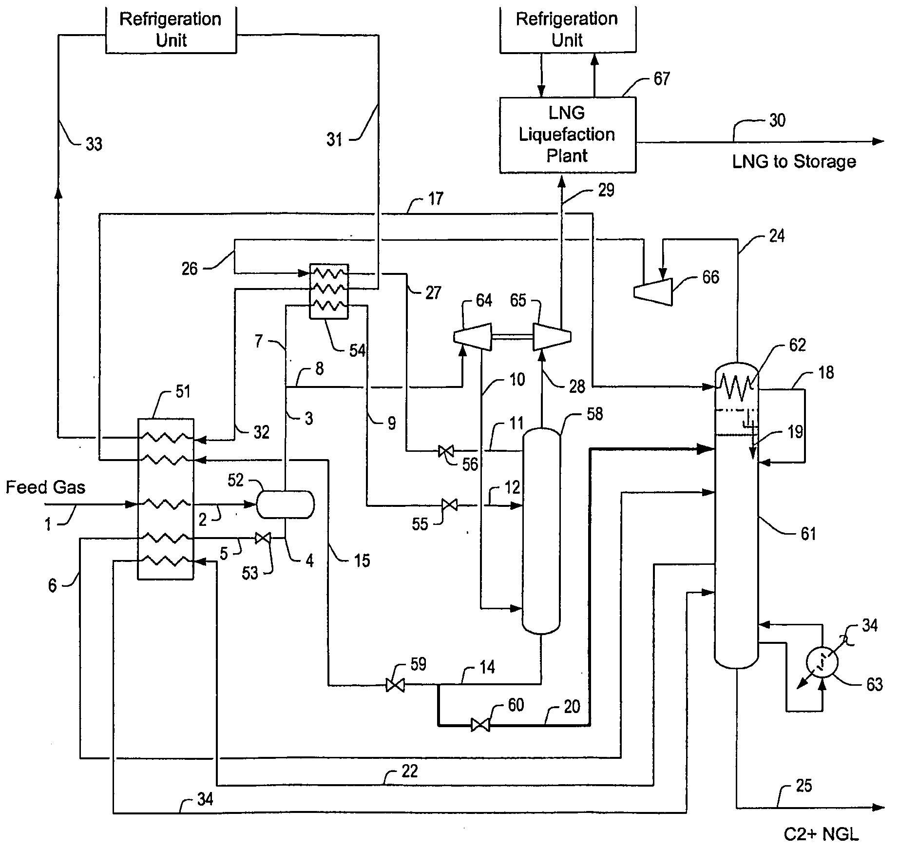
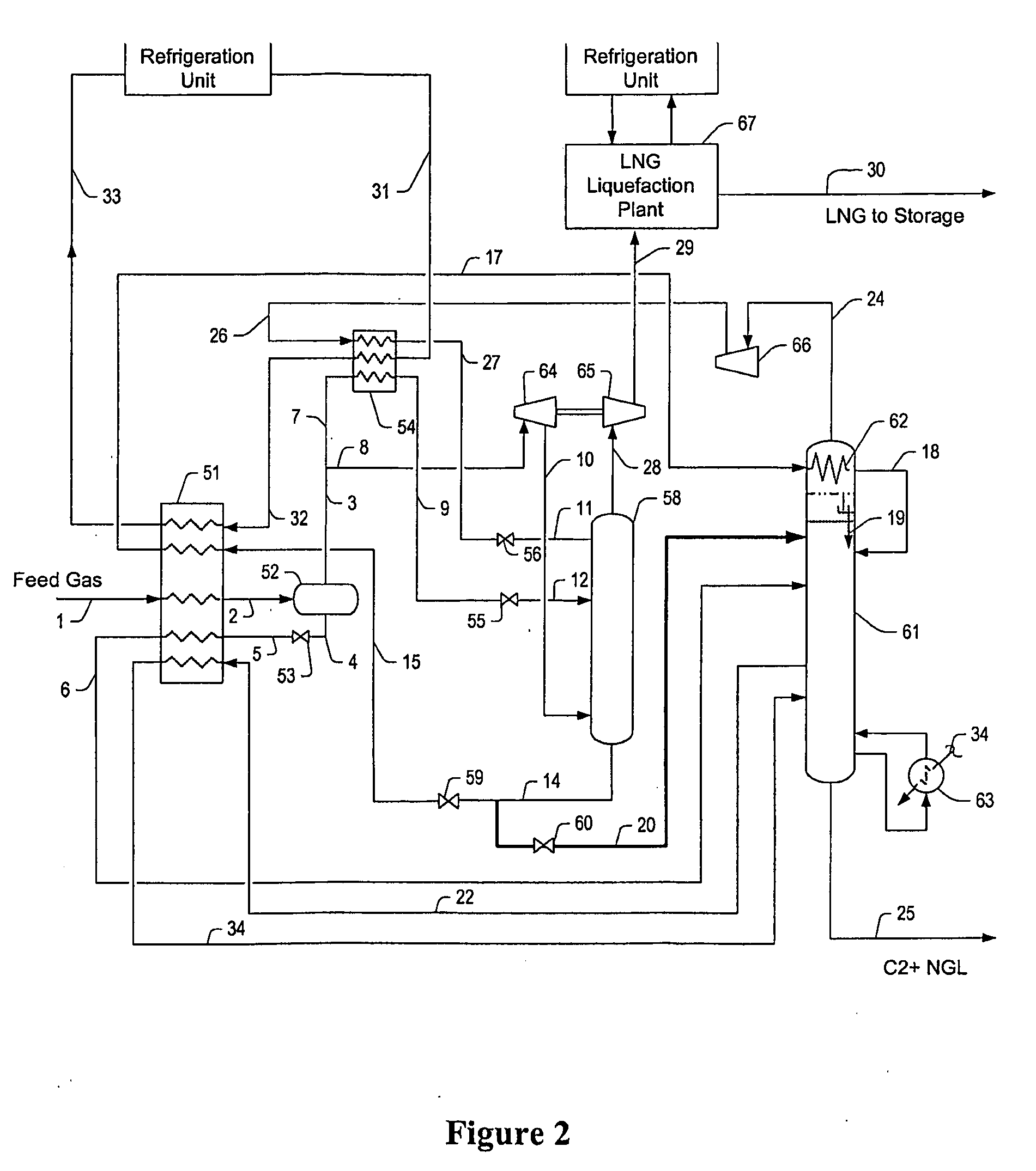
[0023]The inventor has discovered that C2 and C3+ components can be effectively and economically separated from natural gas in a plant (which is preferably coupled to an LNG liquefaction plant) using an absorber that operates at high pressure and produces a cryogenic pressurized lean gas, while a distillation column located downstream of an absorber operates at low pressure and produces the NGL as a bottom product and a reflux stream for the absorber. In especially preferred configurations and methods, recovery of C2 in the NGL can be adjusted by controlling process streams within the plant. Moreover, it should be appreciated that the cryogenic absorber overhead product stream is already at relatively high pressure, and energy for recompression to a pressure suitable for liquefaction is typically provided by expansion of a vapor portion of the natural gas feed stream.

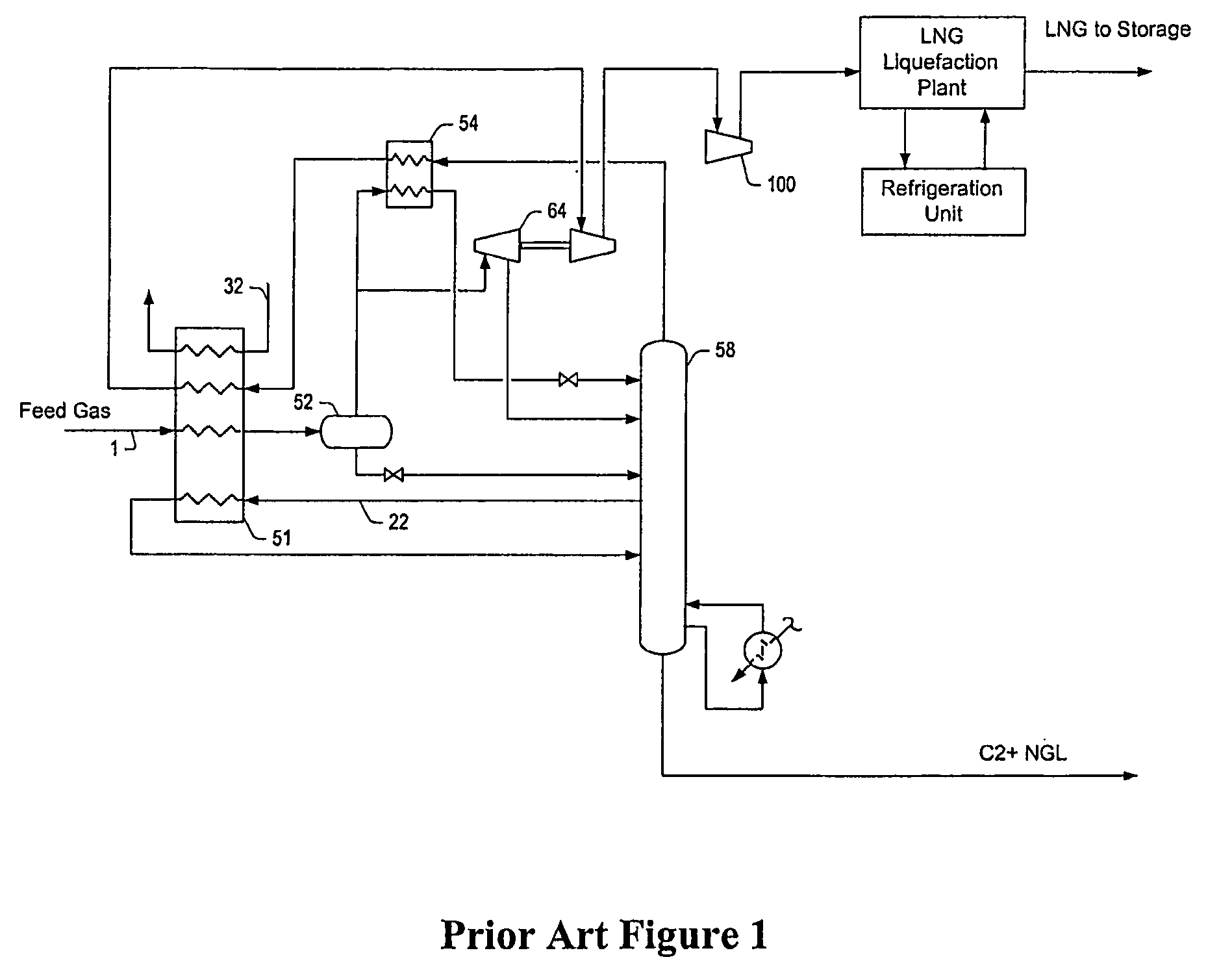
[0024]In contrast, as depicted in Prior Art FIG. 1, a C2 NGL recovery plant has a single column operating at lower pr...


PUM


Abstract

Contemplated plants include a refluxed absorber and a distillation column, wherein the absorber is operated at a higher pressure than the distillation column to thereby produce a cryogenic pressurized lean gas. The lean gas is further compressed to a pressure suitable for liquefaction using energy from feed gas vapor expansion. Desired separation of C2 products is ensured by temperature control of the absorber and distillation column using flow ratios of various streams within the plant, and by dividing the separation process into two portions at different pressures.

Description

[0001]This application claims priority to our copending U.S. provisional patent application with the Ser. No. 60 / 673,518, which was filed Apr. 25, 2005.FIELD OF THE INVENTION[0002]The field of the invention is natural gas liquids (NGL) recovery and LNG liquefaction, and particularly integrated plant configurations for same.BACKGROUND OF THE INVENTION[0003]While the crude oil supply in the world is diminishing, the supply of natural gas is still relatively abundant in many parts of the world. Natural gas is typically recovered from oil and gas production wells located onshore and offshore. Most typically, natural gas predominantly comprises C1 (methane). Depending on the particular formations and reservoirs, natural gas also contains relatively low quantities of non-methane hydrocarbons, including C2, C3, C4, C5, and heavier components. Still further components of natural gas include water, nitrogen, carbon dioxide, hydrogen sulfide, mercaptans, and other gases.[0004]Natural gas from...

Claims


Application Information

Patent Timeline
Patent Type & Authority Applications(United States)
IPC IPC(8): F25J3/00F25J1/00
CPCF25J1/0239F25J3/0209F25J3/0233F25J3/0238F25J2200/04F25J2200/74F25J2200/78F25J2205/04F25J2230/08F25J2230/60F25J2240/02F25J2270/90F25J2280/02F25J2290/10F25J1/0022F25J1/0035F25J1/0255F25J2260/20
Inventor MAK, JOHN
Owner FLUOR TECH CORP
Why Eureka
Try Eureka