Display device and liquid crystal television

a technology of liquid crystal television and display device, which is applied in the direction of measuring device, power supply testing, instruments, etc., to achieve the effect of preventing reverse curren

Inactive Publication Date: 2008-11-06
FUNAI ELECTRIC CO LTD
View PDF5 Cites 1 Cited by
  • Summary
  • Abstract
  • Description
  • Claims
  • Application Information

AI Technical Summary

Benefits of technology

[0011]The display device of the present invention may also have such a constitution that a circuit that generates the constant voltage and the power supply circuit are connected by a diode so that reverse current from the power supply circuit to the circuit that generates the constant voltage is prevented, and the circuit that generates the constant voltage and the optical source lighting circuit are connected by a diode so that reverse current from the optical source lighting circuit to the circuit that generates the constant voltage is prevented.
[0012]Specifically, the diode prevents reverse current to the inspection auxiliary circuit. Therefore, even if a voltage higher than the constant voltage is remaining or generating in the optical source lighting circuit and the power supply circuit, this high voltage does not affect the inspection auxiliary circuit and the source of the external power supply voltage.

Problems solved by technology

However, the techniques disclosed in Japanese Unexamined Patent Publication Nos.

Method used


Image

  • Display device and liquid crystal television
  • Display device and liquid crystal television
  • Display device and liquid crystal television

Examples


Embodiment Construction

[0025]The detailed description set forth below in connection with the appended drawings is intended as a description of presently preferred embodiments of the invention and is not intended to represent the only forms in which the present invention may be constructed and or utilized.

[0026]For purposes of illustration, programs and other executable program components are illustrated herein as discrete blocks, although it is recognized that such programs and components may reside at various times in different storage components, and are executed by the data processor(s) of the computers.

[0027]An embodiment of the present invention will be described below in the order mentioned below.

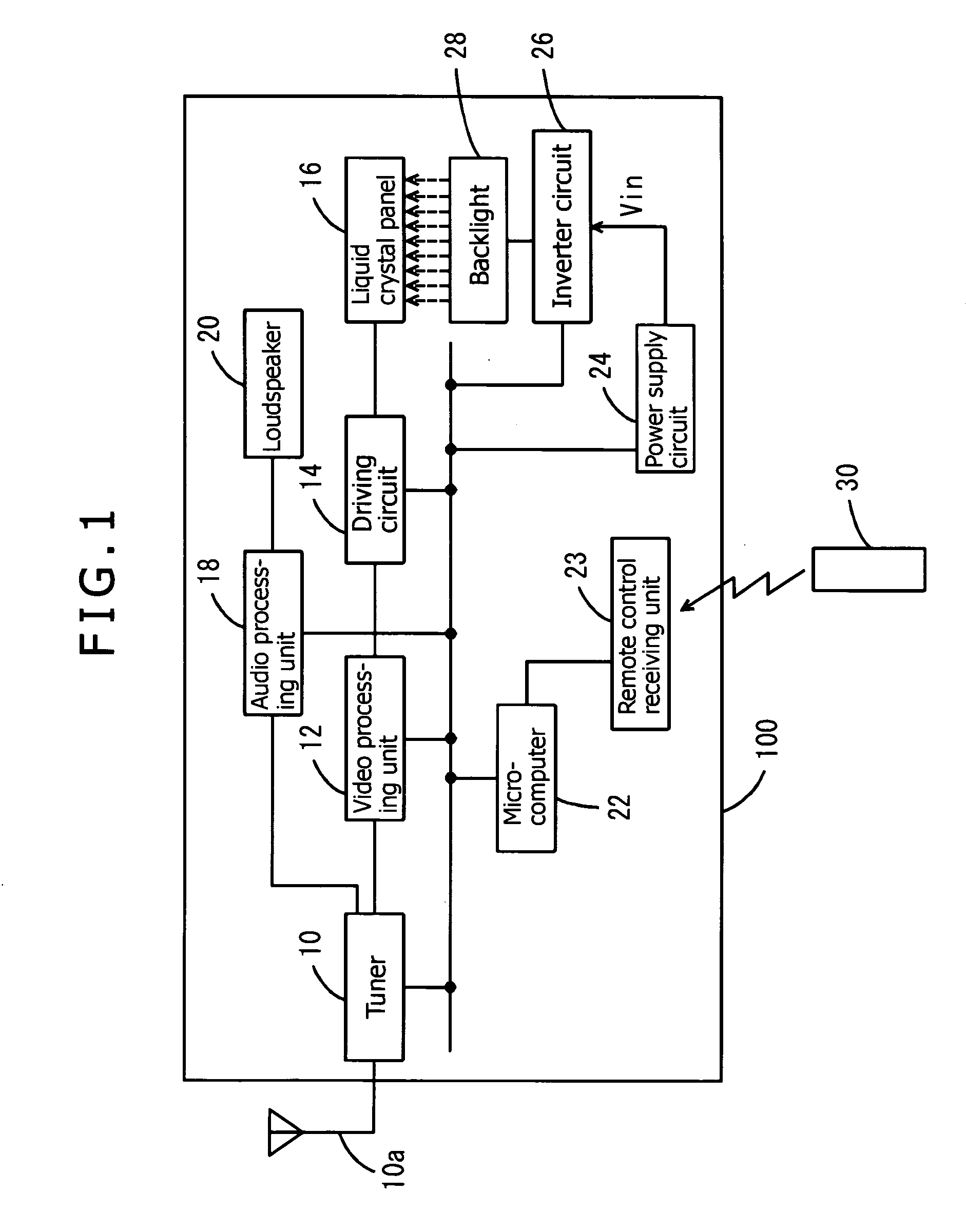
(1) Constitution of liquid crystal television:

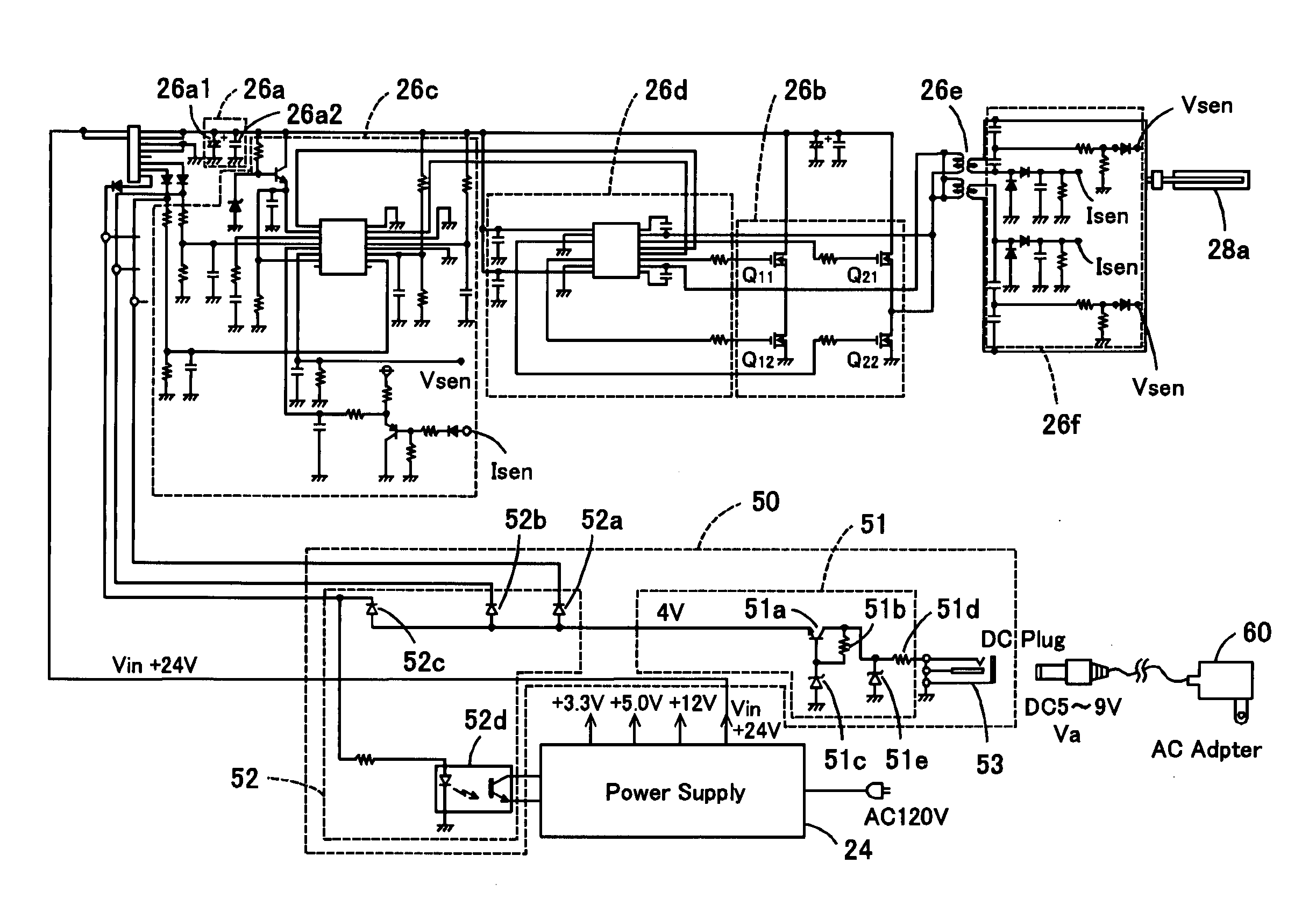
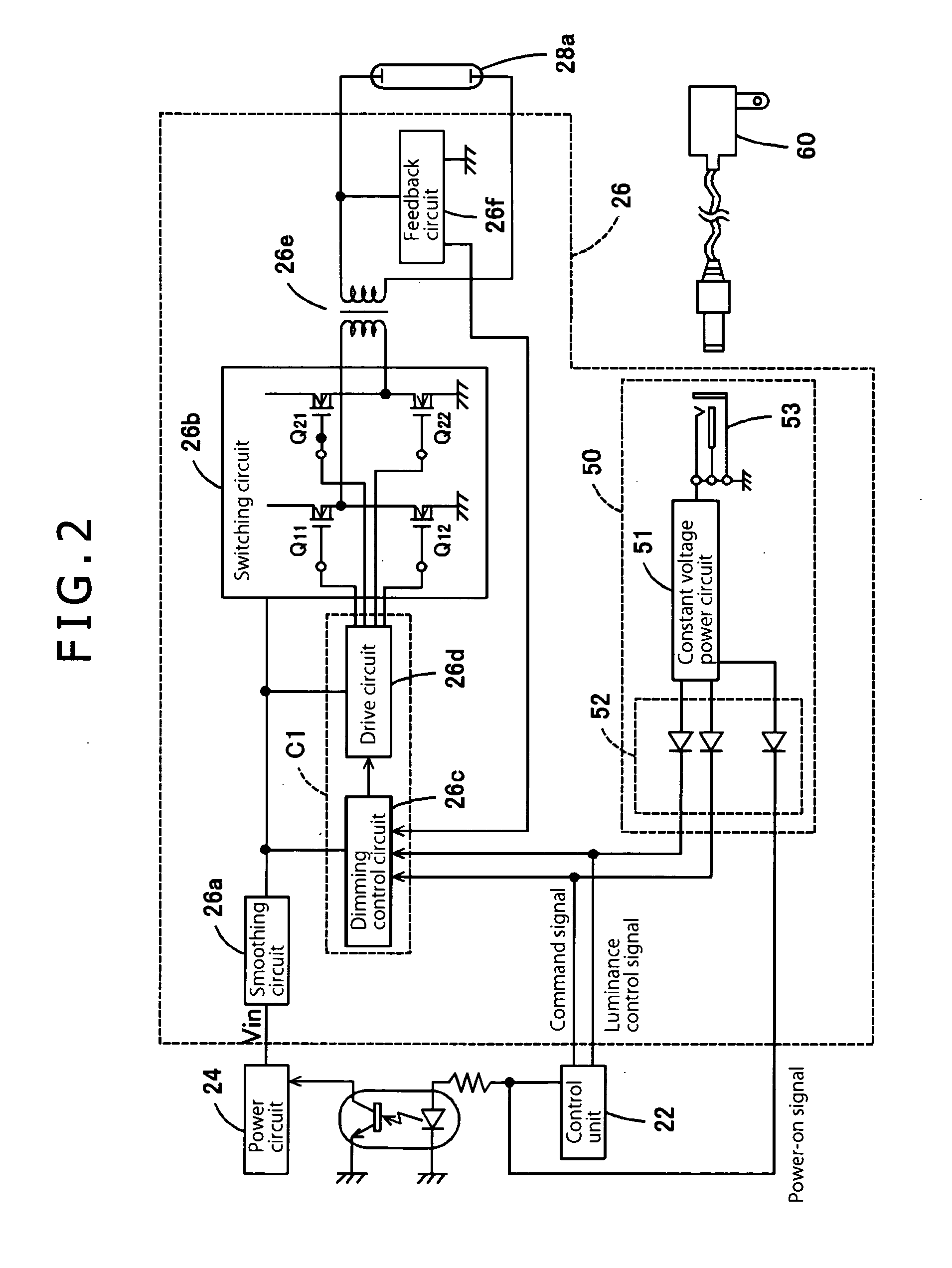
(2) Constitution of inverter circuit:

(3) Constitution of inspection auxiliary circuit:

(4) Conclusion:

(1) CONSTITUTION OF LIQUID CRYSTAL TELEVISION

[0028]An embodiment of the present invention will be described below with reference to FIGS. 1 to 5. In this embodim...


PUM


Abstract

The present invention discloses enabling readily determining which circuit, among a plurality of circuits including an optical source lighting circuit and a power supply circuit, has a failure and repairing the circuits easily in a short period. A liquid crystal television 100 comprising a power supply circuit 24 that produces and outputs various power supply voltages from an inputted commercial AC power supply, a microcomputer 22 that outputs a control signal to a plurality of circuits, respectively, including at least the power supply circuit 24 and an inverter circuit 26 that is driven by a power supply voltage output by the power supply circuit 24 to controls turning on and off of each circuit, is provided with an input terminal 53 for providing a power supply voltage from the outside of the liquid crystal television 100, and an inspection auxiliary circuit 50 connected to the power supply circuit 24 and inverter circuit 26, generating a constant voltage that starts the power supply circuit 24 and inverter circuit 26 when a power supply voltage is provided from the input terminal 53 and outputs the constant voltage as a control signal.

Description

CROSS-REFERENCES TO RELATED APPLICATIONS[0001]The present application is related to the Japanese Patent Application No. 2007-120714, filed May 1, 2007, the entire disclosure of which is expressly incorporated by reference herein.BACKGROUND OF THE INVENTION[0002]1. Field of the Invention[0003]The present invention relates to a display device and a liquid crystal television, particularly to a display device and a liquid crystal television that comprise a power supply circuit that produces and outputs various power supply voltages from an inputted commercial AC power supply, and a control unit that outputs a control signal to a plurality of circuits, respectively, to control startup and shutdown of the circuits, the plurality of circuits comprising at least the power supply circuit and an optical source lighting circuit that is driven by the power supply voltage.[0004]2. Description of Related Art[0005]Circuitry of a display device is normally constituted by combining a plurality of ci...

Claims


Application Information

Patent Timeline
Patent Type & Authority Applications(United States)
IPC IPC(8): G01R31/36
CPCG09G3/006G09G3/3406G09G3/3611G09G2320/0626G09G2330/02
Inventor NISHINOSONO, KAZUO
Owner FUNAI ELECTRIC CO LTD
Why Eureka
Try Eureka