
Systems and Methods for Correcting Errors Resulting from Component Mismatch in a Feedback Path

a feedback path and component technology, applied in the field of audio amplification systems, can solve problems such as expensive solutions, distortion associated with switching, and non-ideal component behavior, and achieve the effect of minimizing performance degradation

Active Publication Date: 2008-11-13
INTERSIL INC
View PDF4 Cites 25 Cited by
  • Summary
  • Abstract
  • Description
  • Claims
  • Application Information

AI Technical Summary

Benefits of technology

[0010]One or more of the problems outlined above may be solved by the various embodiments of the invention. Broadly speaking, the invention comprises systems and methods for minimizing performance degradation due to component mismatch in the feedback path of a digital PWM amplifier feedback loop.
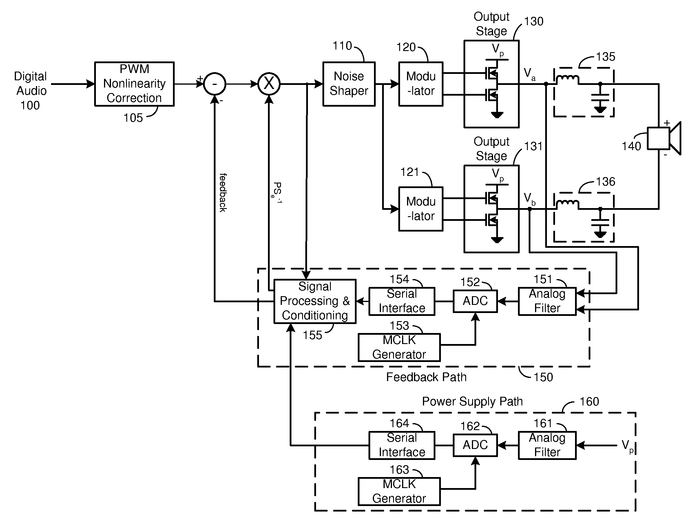
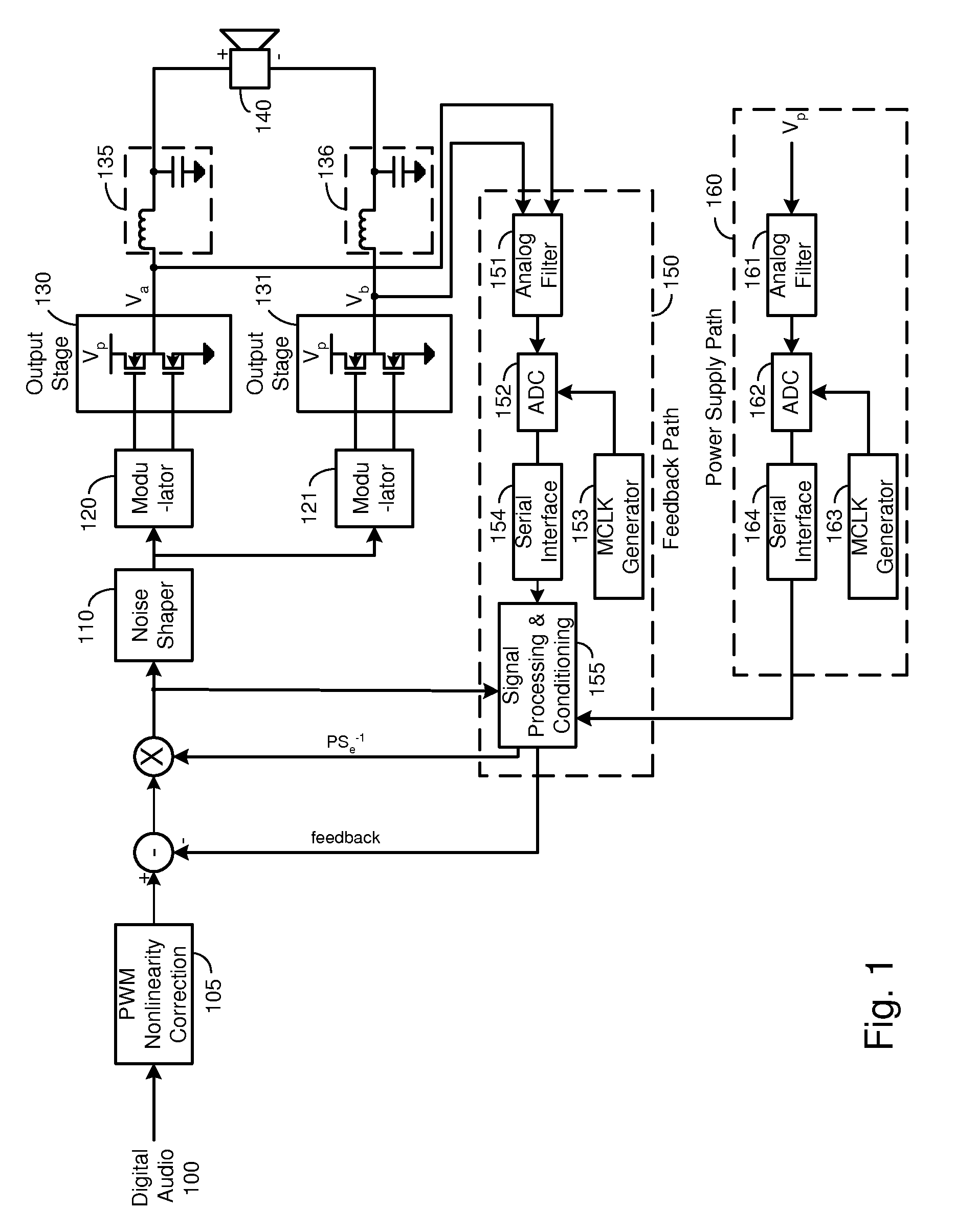
[0014]Another embodiment comprises a method implemented in a digital PWM amplifier having a feedback loop. The method includes producing an analog output signal based on a digital audio signal, filtering the analog output signal to produce a feedback signal, scaling a power supply measurement and adding the scaled power supply measurement to the feedback signal to reduce component mismatch errors in the feedback signal. In one embodiment, the analog output signal is produced by performing PWM non-linearity correction on the digital audio signal, adding the feedback signal with the scaled power supply measurement to the digital audio signal, quantizing and noise shaping the digital audio signal, generating PWM waveforms from the quantized digital audio signal, and generating the analog output audio based on the PWM waveforms. In one embodiment, the feedback signal and the power supply measurement are digitized and decimated before adding the scaled power supply measurement to the feedback signal. In one embodiment, the method includes determining the gain for scaling the power supply measurement, including the steps of providing an input tone to the amplifier, selecting a feedback loop gain at which the open-loop output amplitude is approximately equal to the closed-loop output amplitude, closing the feedback loop, and selecting the power supply gain at which the measured value of total harmonic distortion plus noise is minimized.

Problems solved by technology

It is possible to obtain extremely good performance when such amplifiers are run ‘open-loop’, that is without feedback, but it is an expensive solution, since the amplifier's performance is critically dependent on the quality of the output stages and the power supply.
The digital principle brings precision to the generation of the PWM waveform, but the power amplification, typically accomplished by MOSFET (Metal Oxide Silicon Field Effect Transistors) power switches, remains a fundamentally analog process, and as such is vulnerable to non-ideal component behavior.
There is a distortion associated with the switching called “dead-time distortion”, and there is dependency on the power supply, just as with the original analog PWM amplifiers.
This precludes the use of an inexpensive non-regulated power supply in low-cost applications, or condemns the system to relatively poor performance.

Method used


Image

  • Systems and Methods for Correcting Errors Resulting from Component Mismatch in a Feedback Path
  • Systems and Methods for Correcting Errors Resulting from Component Mismatch in a Feedback Path
  • Systems and Methods for Correcting Errors Resulting from Component Mismatch in a Feedback Path

Examples


Embodiment Construction

[0023]One or more embodiments of the invention are described below. It should be noted that these and any other embodiments described below are exemplary and are intended to be illustrative of the invention rather than limiting.

[0024]As described herein, various embodiments of the invention comprise systems and methods for minimizing performance degradation due to component mismatch in the feedback path of a digital PWM amplifier feedback loop. One embodiment of the invention is implemented in a digital Class D pulse width modulated (PWM) amplifier that utilizes feedback as described by Andersen et al. In this embodiment, the amplified output of the amplifier's full-bridge output stage is filtered using analog filtering techniques and sampled by an analog to digital converter (ADC) before the passive inductor-capacitor filter that couples the output to a loudspeaker. The ADC's digital output is transported by a serial interface to a processing unit such as a decimation filter. The p...


PUM


Abstract

Systems and methods for minimizing performance degradation due to component mismatch in the feedback path of a digital PWM amplifier feedback loop. One embodiment comprises a digital pulse width modulated (PWM) amplifier with feedback. The amplification subsystem receives a digital audio signal and produces an analog output signal. The feedback loop produces a feedback signal based on the filtered analog output signal and modifies the digital audio signal based on the feedback signal. The feedback loop includes a filter configured to filter the analog output signal and correction circuitry configured to correct component mismatch errors introduced by the filter. In one embodiment, the correction circuitry receives a measurement of a power supply voltage, multiplies the measured voltage by a gain and adds the scaled measurement to the feedback signal to correct for the component mismatch errors.

Description

RELATED APPLICATIONS[0001]This application claims the benefit of U.S. Provisional Patent Application 60 / 771,147, filed Feb. 7, 2006, which is incorporated by reference as if set forth herein in its entirety. This application is related to U.S. patent application Ser. No. ______, entitled “Power Supply Feed Forward Analog Input Filter Component Mismatch Correction”, by Kost, et al., filed Feb. 7, 2007 (Attorney docket D2A1420-1), which is incorporated by reference as if set forth herein in its entirety.BACKGROUND[0002]1. Field of the Invention[0003]The invention relates generally to audio amplification systems, and more particularly to systems and methods for minimizing performance degradation due to component mismatch in the feedback path of a digital PWM amplifier feedback loop.[0004]2. Related Art[0005]Practical audio power amplifiers using Pulse Width Modulation (PWM) have been known since the mid 1960s. In amplifiers from that era, a pulse train was generated by comparing a volt...

Claims


Application Information

Patent Timeline
IPC IPC(8): H03F3/38
CPCH03F1/30H03F1/34H03F3/2173H03F2200/03H03F2200/351
Inventor KOST, MICHAEL A.ANDERSEN, JACK B.CHIENG, DANIEL L.W.
Owner INTERSIL INC
Learn More