Method of preparing carbon nanotube containing electrodes
- Summary
- Abstract
- Description
- Claims
- Application Information
AI Technical Summary
Problems solved by technology
Method used
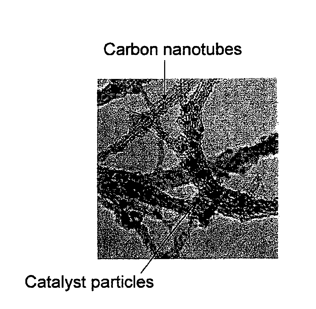
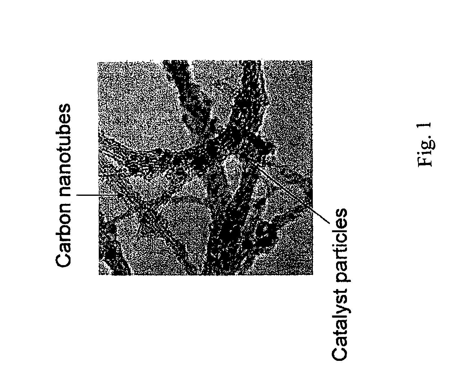
Image

Examples
example 1
[0053]Iron acetate (Fe(OOCCH3)2 (Alpha AESAR) can be mixed into methanol and a separate suspension of alumina (Alpha AESAR) in methanol can also be prepared and then the two solutions mixed thoroughly for one hour. The molar ratio between the iron and the alumina can be about 1:30. The solvent can then be evaporated and the remaining mass heated to 120 C for 3 hours under a nitrogen gas flow. The dried mass can be allowed to cool and then ground in an agate mortar. The powder can then be calcined for 1 hour at 500 C and then ground and loaded into a quartz tube flow reactor of a chemical vapor deposition (“CVD”) apparatus.
[0054]Argon gas can be passed over the ground powder in the reactor as the temperature can then be raised at 10 C / minute until a steady temperature of 820 C is reached. A mixture of methane (40 sccm) diluted in argon (200 sccm) can then be passed over the catalyst powder for 60 minutes.
[0055]The resulting material can be studied by Raman spectroscopy and TEM to con...
example 2
[0056]Iron acetylacetonate (Fe(CH3COCHCOCH3)3 (Alpha AESAR) can be mixed into methanol and a separate suspension of magnesia (Alpha AESAR) in methanol can also be prepared and then the two solutions mixed thoroughly for one hour. The molar ratio between the iron and the magnesia can be about 1:25. The solvent can then be evaporated and the remaining mass heated to 120 C for 3 hours under a nitrogen gas flow. The dried mass can be allowed to cool and then ground in an agate mortar. The powder can then be calcined for 1 hour at 500 C and then ground and loaded into a quartz tube flow reactor of a CVD apparatus.
[0057]The ground powder can then be reduced in situ by flowing a gas mixture of 40 sccm H2 and 100 sccm He at 500 C for 1 hour. Then, argon gas can be passed over the catalyst in the reactor as the temperature can then be raised at 10 C / minute until a steady temperature of 820 C is reached. A mixture of methane (40 sccm) diluted in argon (200 sccm) can then be passed over the ca...
example 3
[0059]Iron acetate (Fe(OOCCH3)2 (Alpha AESAR) can be mixed into glycol at a 1:15 molar concentration ratio and then can be heated to 150 C under nitrogen for twenty minutes to form iron nanoparticles. The reaction mixture can be allowed to cool to room temperature and then alumina (Alpha AESAR) can be added to the iron / glycol mixture in a molar ratio of 1:30 metal:alumina. The solution can be stirred for four hours, and then the solvent can be removed by flowing nitrogen gas. The dried mass can be collected then can be loaded into a quartz tube flow reactor of a CVD apparatus.
[0060]The catalyst can then be reduced in situ by flowing a gas mixture of 40 sccm H2 and 100 sccm He at 500 C for 1 hour. Then, argon gas can be passed over the catalyst in the reactor as the temperature can then be raised at 10 C / minute until a steady temperature of 820 C is reached. A mixture of methane (40 sccm) diluted in argon (200 sccm) can then be passed over the catalyst powder for 30 minutes.
[0061]The...
PUM
| Property | Measurement | Unit |
|---|---|---|
| Diameter | aaaaa | aaaaa |
| Diameter | aaaaa | aaaaa |
| Diameter | aaaaa | aaaaa |
Abstract
Description
Claims
Application Information
 - Generate Ideas
- Intellectual Property
- Life Sciences
- Materials
- Tech Scout
- Unparalleled Data Quality
- Higher Quality Content
- 60% Fewer Hallucinations
Browse by: Latest US Patents, China's latest patents, Technical Efficacy Thesaurus, Application Domain, Technology Topic, Popular Technical Reports.
© 2025 PatSnap. All rights reserved.Legal|Privacy policy|Modern Slavery Act Transparency Statement|Sitemap|About US| Contact US: help@patsnap.com