Multi-processor device
a multi-processor device and bus configuration technology, applied in the direction of multiple processing unit architecture, generating/distributing signals, instruments, etc., can solve the problems of cpus having to wait long, deteriorating the performance of high-speed processors, and impaired operation of high-speed processors, so as to reduce the coordination and bus contention between processors, low cost, and low power
- Summary
- Abstract
- Description
- Claims
- Application Information
AI Technical Summary
Benefits of technology
Problems solved by technology
Method used
Image
Examples
embodiment 1
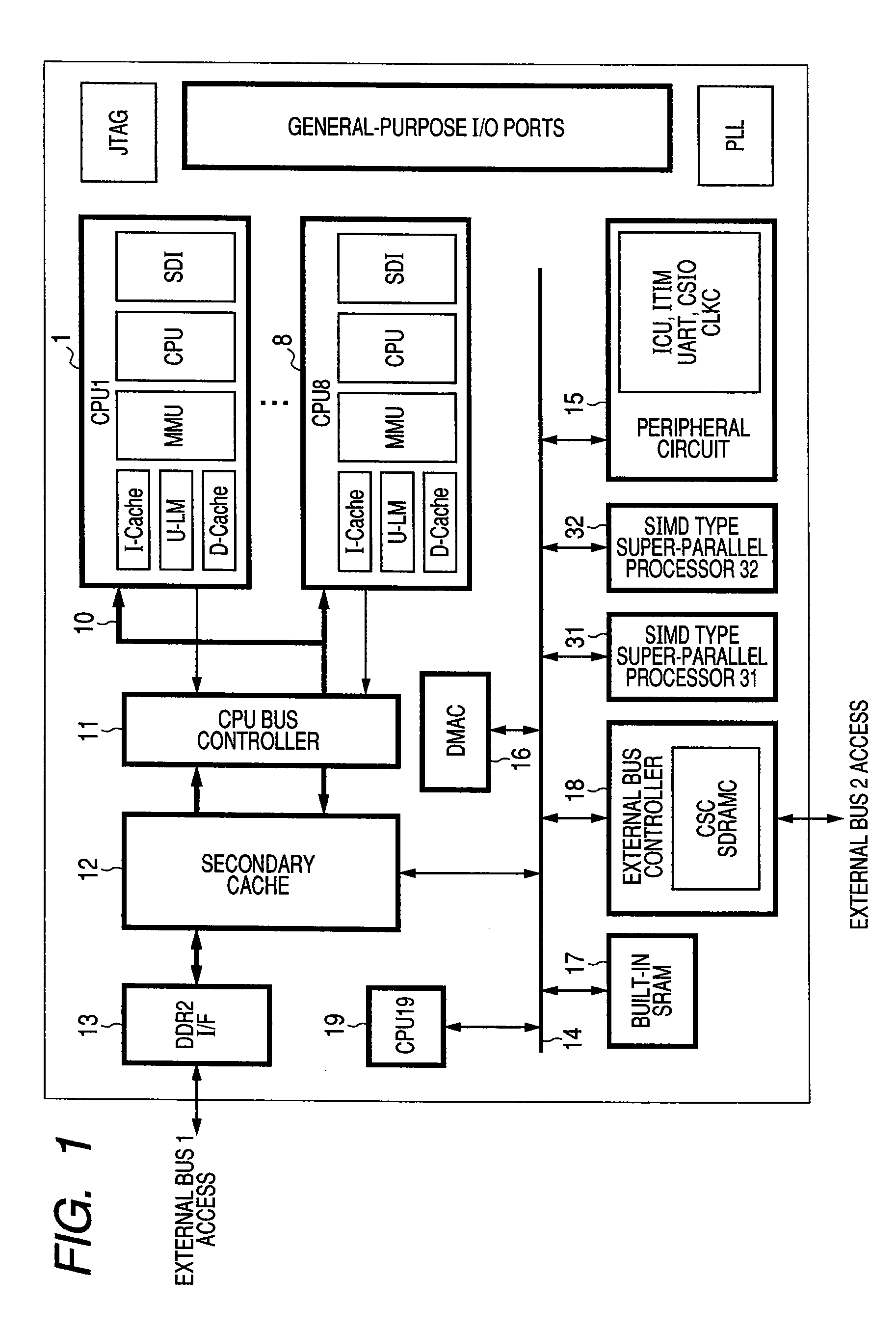
[0027][Embodiment 1]FIG. 1 is a diagram showing a configuration of a multi-processor device of Embodiment 1 of the present invention. This multi-processor device is formed over a single semiconductor chip 1. Multiple processors, namely, CPUs CPU1 through CPU8 are arranged in parallel (a first group of processors), making a Symmetric Multiple Processor (SMP) structure. Each CPU includes primary caches (I-cache, D-cache), a local memory (U-LM), a memory management unit (MMU), and a debugger (SDI). Eight CPUs are coupled to a CPU bus 10 (a first bus) and the CPU bus 10 is coupled to a secondary cache 12 via a CPU bus controller 11. The secondary cache 12 is coupled to an external bus 1 via a DDR2 I / F 13 (a first external bus interface).
[0028]The CPUs operate internally at 533 MHz at maximum. The operating frequency of each CPU is converted by a bus interface inside the CPU, so that the CPU is coupled to the CPU bus 10 at 266 MHz at maximum. The secondary cache 12 and the DDR2 I / F 13 op...
embodiment 2
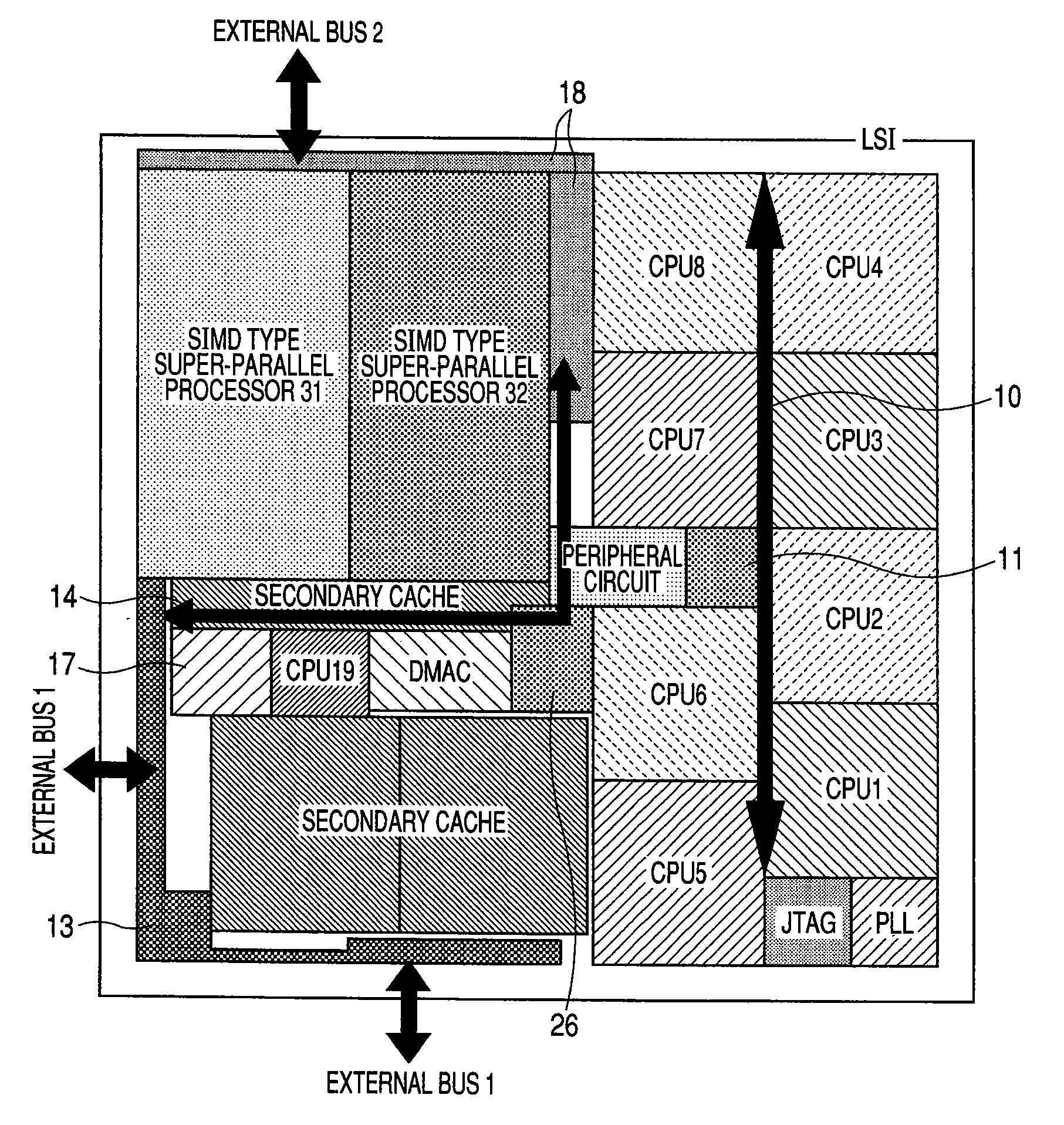
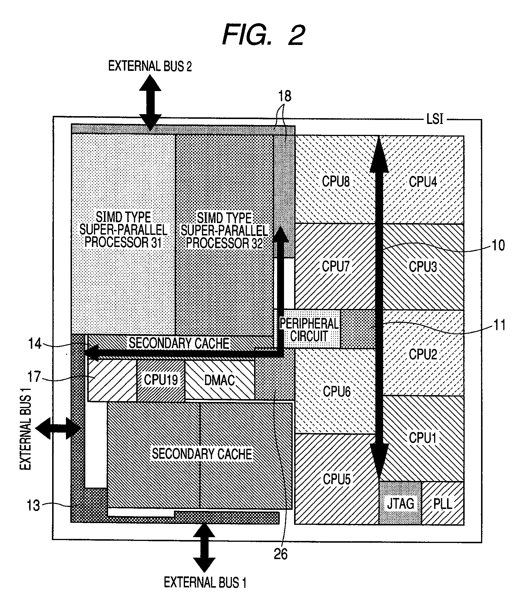
[0035][Embodiment 2]FIGS. 2 through 4 are layout views of components of the multi-processor device in Embodiment 2 of the present invention. FIG. 2 illustrates an example of layout in which the modules constituting the multi-processor device of Embodiment 1 are actually arranged over a silicon wafer. FIG. 3 presents the layout example of FIG. 2 in another view in which the modules associated to the CPU bus (CPUs CPU1 through CPU 8 and CPU bus controller) are represented collectively as a CPU bus region 20 and the modules associated to the internal peripheral bus (SIMD type super-parallel processors 31, 32, CPU 19, built-in SRAM 17, peripheral circuit 15, external bus controller 18, and DMAC 16) are represented collectively as an internal peripheral bus region 21. FIG. 4 is a layout view in which supply voltage / GND lines 2-2 are wired.
[0036]By laying out the components of the multi-processor device as illustrated in FIG. 2, the internal peripheral bus 14 and the CPU bus 10 can be run...
embodiment 3
[0042][Embodiment 3]FIG. 5 is an example of layout of the modules of the multi-processor device of Embodiment 1 configured on an actual silicon wafer. In comparison with Embodiment 2, changes are the positional relationship between the CPU bus controller module and the peripheral circuit module, the position and size of the built-in SRAM 17, and the shapes of the CPU 19 and the secondary caches 12.
[0043]As regards the positional relationship between the CPU bus controller module, in most cases of layout using an automatic wiring tool, buses are wired between each CPU and the CPU bus controller module as shown in FIG. 5, not a straight bus wiring that divides the CPU region into exactly two parts as shown in FIG. 2. In such cases, although some of the CPU buses slightly overlap with the internal peripheral bus 14, almost the same effect as in Embodiment 2 can be obtained. It may be preferred to place the CPU bus controller module in the vicinity of the centroid of the area compassing...
PUM
 Abstract
Description
Claims
Application Information
 - R&D
- Intellectual Property
- Life Sciences
- Materials
- Tech Scout
- Unparalleled Data Quality
- Higher Quality Content
- 60% Fewer Hallucinations
Browse by: Latest US Patents, China's latest patents, Technical Efficacy Thesaurus, Application Domain, Technology Topic, Popular Technical Reports.
© 2025 PatSnap. All rights reserved.Legal|Privacy policy|Modern Slavery Act Transparency Statement|Sitemap|About US| Contact US: help@patsnap.com


