
Device for the generation of a gas curtain for plasma-based EUV radiation sources

Active Publication Date: 2008-11-20
USHIO DENKI KK
View PDF3 Cites 21 Cited by
  • Summary
  • Abstract
  • Description
  • Claims
  • Application Information

AI Technical Summary

Benefits of technology

[0018]It is the primary object of the invention to find a novel possibility for generating a gas curtain in the immediate vicinity of a radiating plasma so as to permit a simple arrangement and design and a long life of the device for generating the gas curtain under extreme thermal stress.
[0031]Further, in an arrangement for generating EUV radiation based on a gas discharge in which an electrode arrangement for generating a gas discharge plasma and collector optics for collecting along an optical axis the EUV radiation emitted from the plasma are arranged in a vacuum chamber and a slit nozzle for generating a gas curtain is arranged orthogonal to the optical axis between the plasma and collector optics, the above-mentioned object is met in that the slit nozzle has at least one gas outlet part made of high-melting material and additional parts for the gas inlet are produced from material which is easily workable with respect to high-precision mechanics, and the slit nozzle is fastened at least partially in a radiation shadow of the electrode arrangement provided for generating plasma, and a suction device for the gas curtain is arranged opposite to the optical axis of the collector optics, likewise in the radiation shadow.
[0037]The solution according to the invention makes it possible to realize a gas curtain in the immediate vicinity of a radiating plasma, which permits a simple arrangement and design and a long life of the slit nozzle under extreme thermal stresses. Further, the solution is suitable for different modes of generating EUV radiation-emitting plasma and, in addition to suppression of debris, enables a spectral filtering of the generated radiation in the same way.

Problems solved by technology

The spatial resolution that can be achieved by this method is limited by the wavelength of the light that is used.
Depending on the operating parameters, the emitted debris leads to abrasion of reflecting layers, deposits of impurities, or a coarsening of the optical surface.
All of these processes reduce the reflectivity of the optics.
However, the problem with using a gas curtain is that its extension (within a plane) is spatially limited so that the generating slit nozzle must be moved as close as possible to the plasma in order to cover a large solid angle of the EUV radiation.
This results in a high thermal stress on the nozzle.
However, supersonic slit nozzles comprise extremely precise, highly engineered shapes which are difficult to cool and extremely difficult to produce from high-melting materials (e.g., tungsten or molybdenum).

Method used


Image

  • Device for the generation of a gas curtain for plasma-based EUV radiation sources
  • Device for the generation of a gas curtain for plasma-based EUV radiation sources
  • Device for the generation of a gas curtain for plasma-based EUV radiation sources

Examples


Embodiment Construction

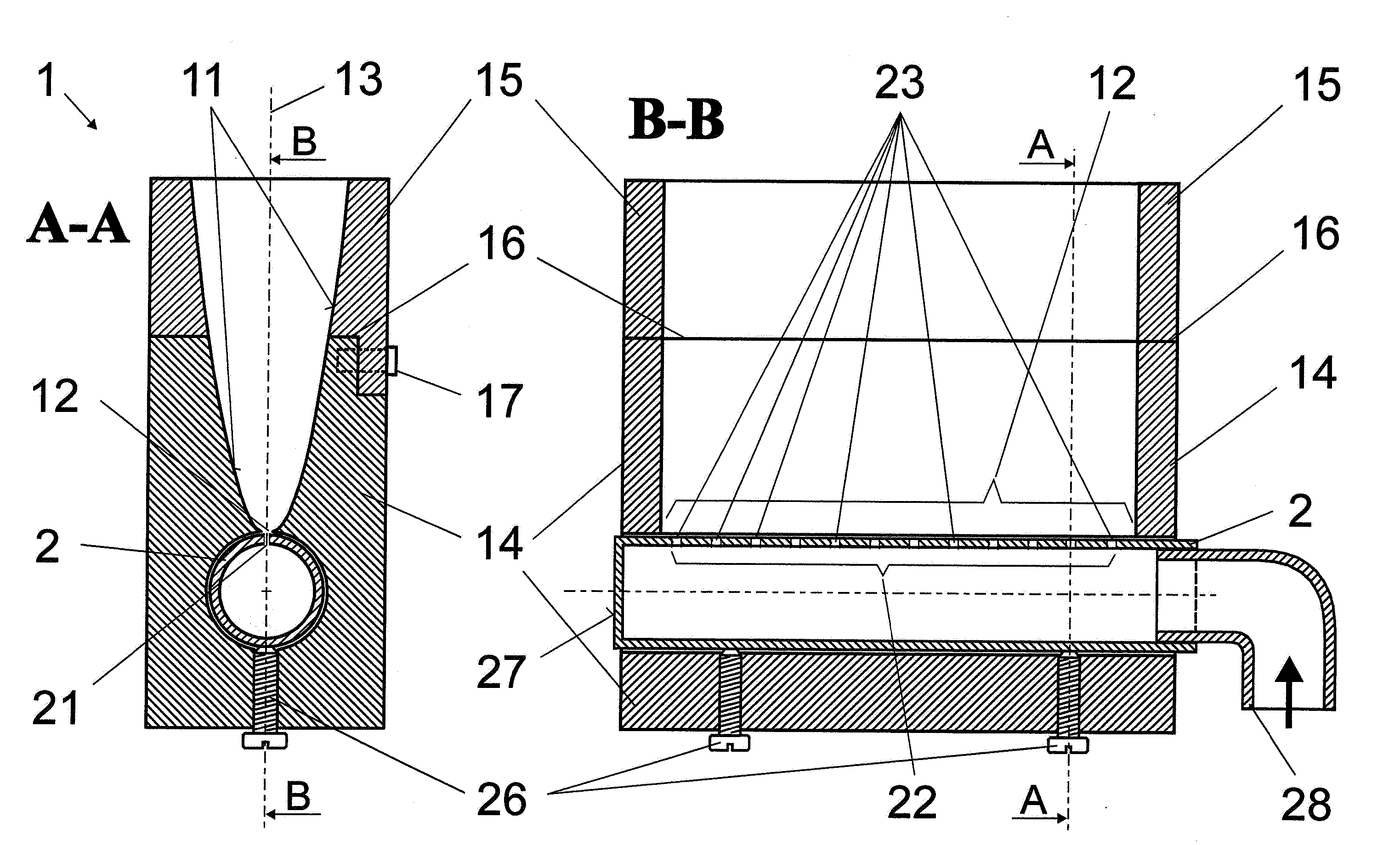
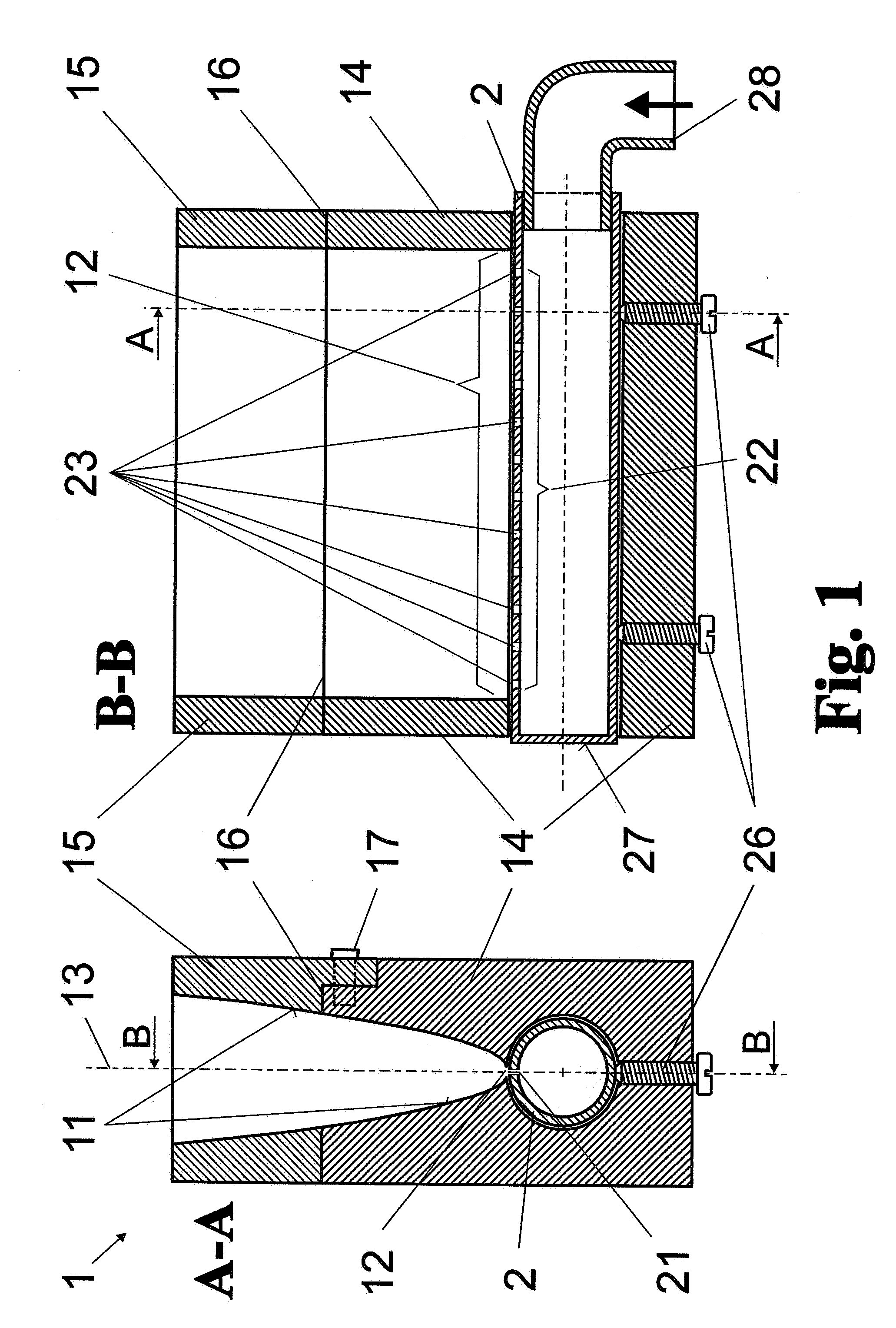
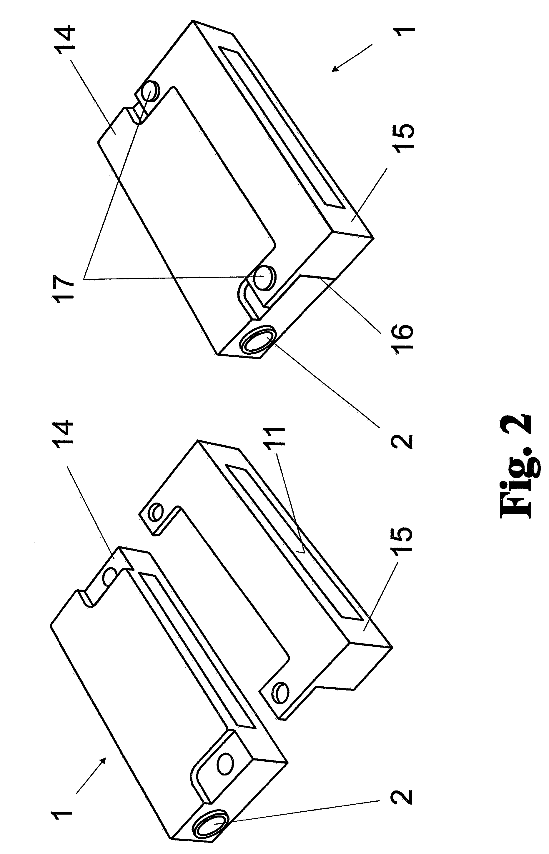
[0045]FIG. 1 shows the construction of a slit nozzle 1 according to the invention in cross section and in longitudinal section. The slit nozzle 1 for forming a supersonic nozzle with a slit-shaped nozzle profile 11 is divided with respect to the gas outlet direction and comprises at least one gas inlet part 14 and a gas outlet part 15. The gas outlet part 15 is manufactured from a heat-resistant material (such as tungsten, molybdenum, or the like) in view of the high thermal loading because of its immediate proximity to the plasma. The gas inlet part 14 of the slit nozzle 1 is made of a material which is not quite as resistant to heat but which can be machined more easily (e.g., stainless steel). Both parts 14 and 15 must be adapted to one another in such a way that the gas inlet part 14 and gas outlet part 15 form a nozzle profile 11 with a joint 16 that is as closed as possible so as not to generate a tear-off edge for the gas flow. The slit nozzle 1 has an entrance slit 12 for th...


PUM


Abstract

The invention is directed to a device for generating flows of gas for filtering the radiation emitted in plasma-based radiation sources. It is the object of the invention to find a novel possibility for generating a gas curtain in the immediate vicinity of a radiating plasma so as to permit a simple arrangement and design and a long life of the device for generating the gas curtain under extreme thermal stress. According to the invention, this object is met in that a slit nozzle is formed of a plurality of partial bodies comprising different materials to form a supersonic nozzle profile for the generation of a broad gas curtain in order to accommodate the slit nozzle to different thermal and precision-mechanical requirements in the gas inlet region and in the gas outlet region.

Description

CROSS-REFERENCE TO RELATED APPLICATIONS[0001]This application claims priority of German Application No. 10 2007 023 444.0, filed May 16, 2007, the complete disclosure of which is hereby incorporated by reference.BACKGROUND OF THE INVENTION[0002]a) Field of the Invention[0003]The invention is directed to a device for generating flows of gas for filtering the radiation emitted in plasma-based radiation sources in which at least one supersonic slit nozzle is provided for generating a gas curtain in the beam bundle that can be coupled out.[0004]b) Description of the Related Art[0005]The invention is preferably applied in semiconductor chip fabrication in radiation sources for EUV lithography for protecting the collector optics and other optics downstream of the latter from debris.[0006]As per the current state of the art, the structuring of semiconductor chips is carried out by means of optical lithography. To this end, the desired structure contained on a mask is imaged onto a semicond...

Claims


Application Information

Patent Timeline
IPC IPC(8): G02B5/00
CPCG03F7/70916G03F7/70908
Inventor TRAN, CHINH DUCBRUDERMANN, JESKOMADER, BJOERNDORNIEDEN, GILBERTBRAUNER, THOMAS
Owner USHIO DENKI KK
Learn More