Method for on-line measurement of battery internal resistance, current operational module, and on-line measurement instrument for battery internal resistance
- Summary
- Abstract
- Description
- Claims
- Application Information
AI Technical Summary
Benefits of technology
Problems solved by technology
Method used
Image
Examples
embodiment 1
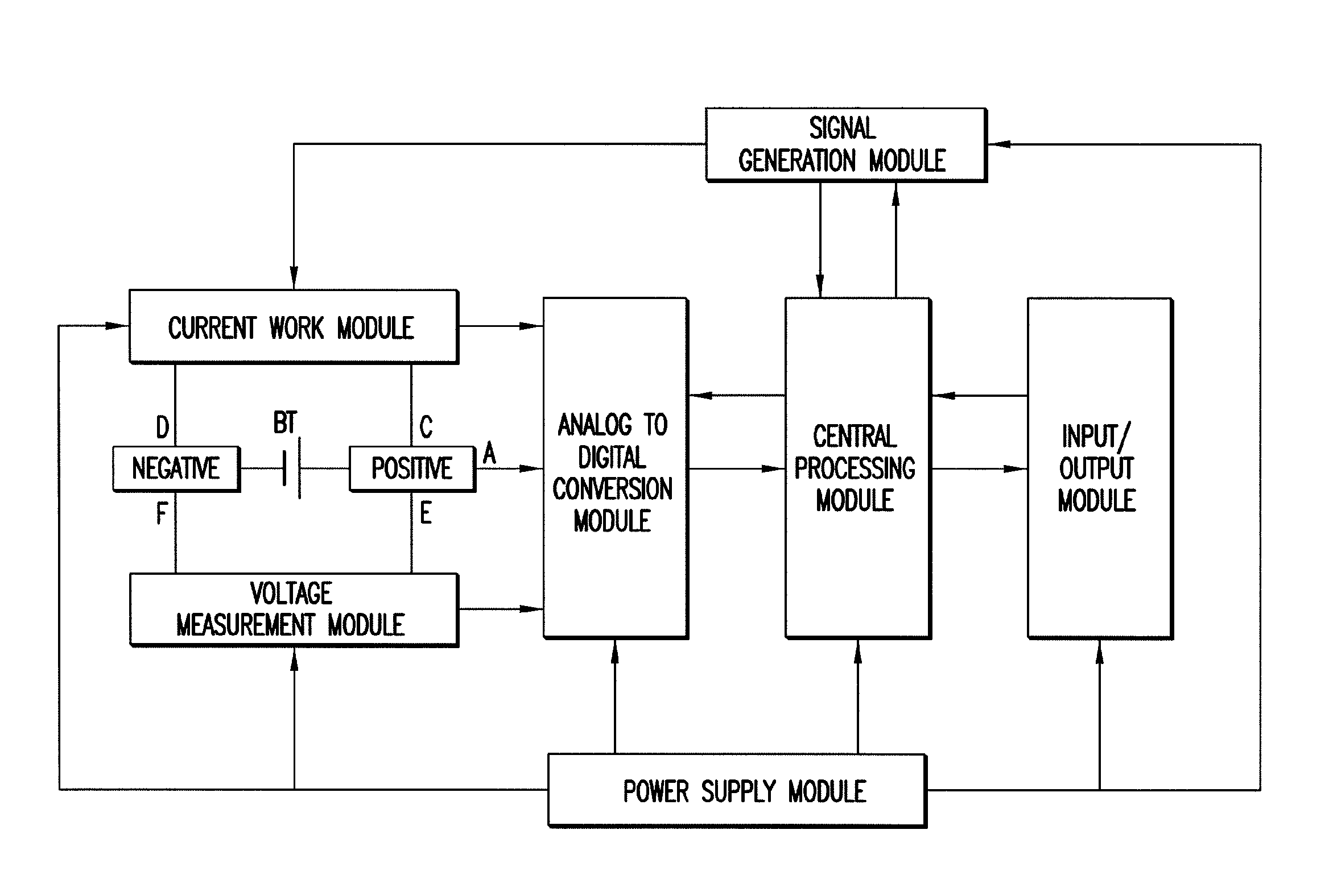
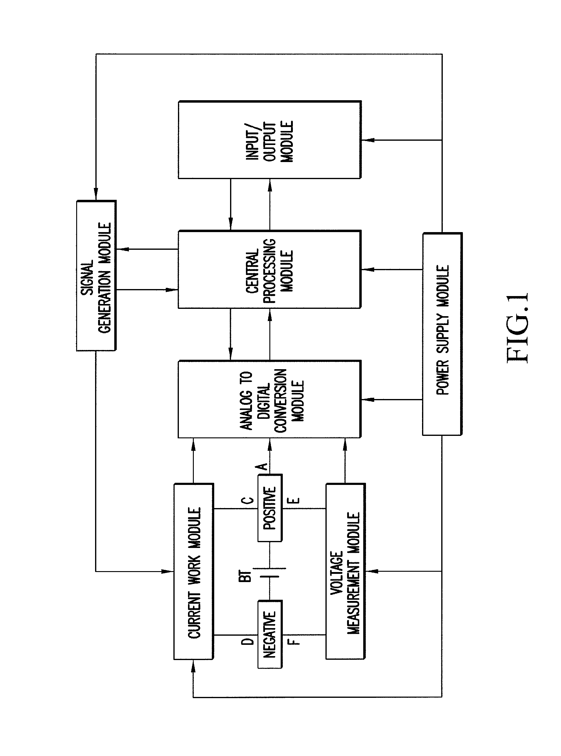
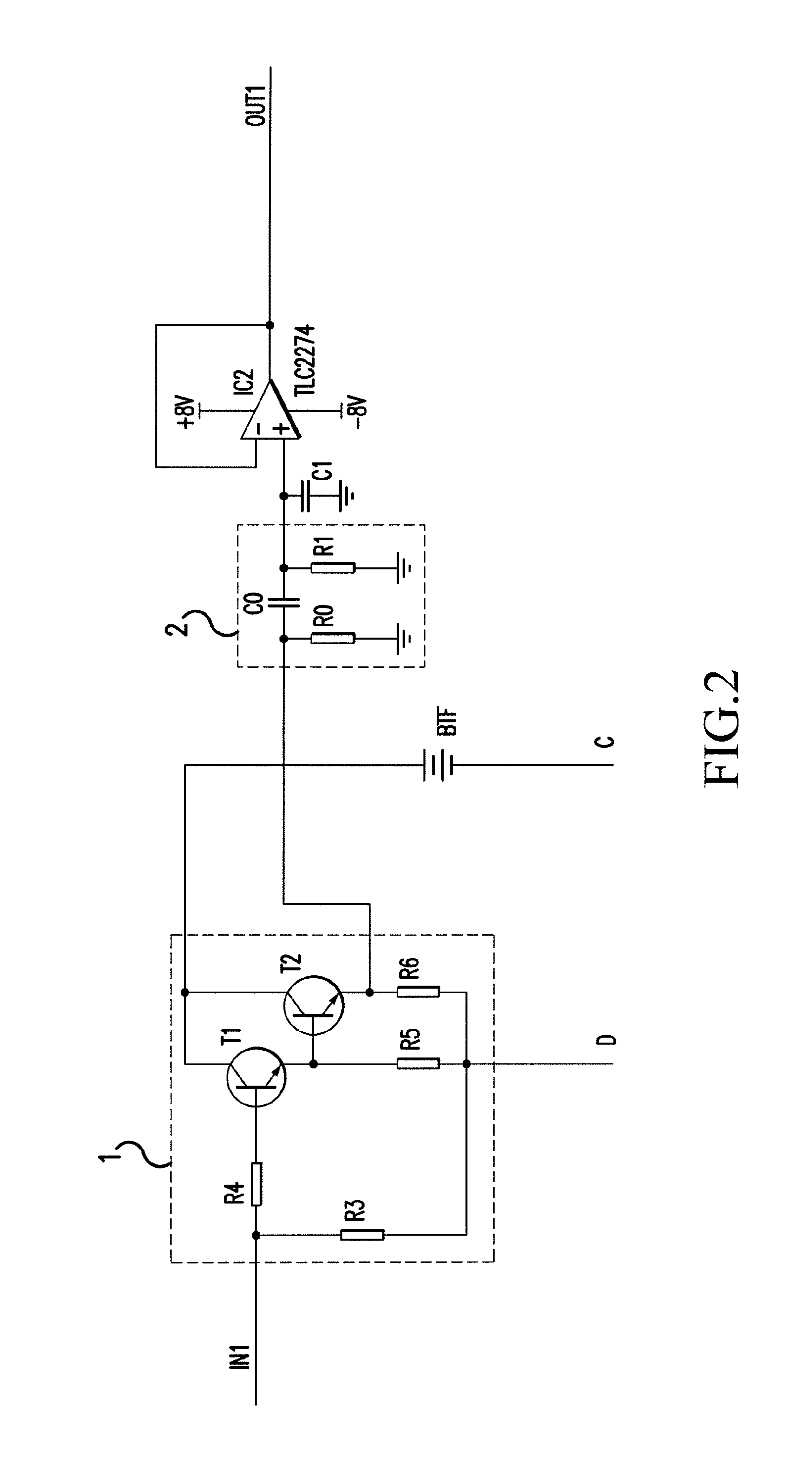
[0041]With Reference to FIG. 1, FIG. 2, FIG. 6-10, FIG. 12, a current operational module for on-line measurement of battery internal resistance, comprises a load circuit 1 discharging with a pulse DC, an auxiliary power supply BTF and a stopping circuit 2, the pulse DC has a DC component and a sine AC component, the load circuit 1 and the auxiliary power supply BTF are connected in series, the output of the load circuit 1 is connect with the input of the stopping circuit 2.
[0042]The load circuit 1 comprises a triode T1 and a triode T2, the input of the load circuit 1 is connected with the base of the triode T1 through resistor R4, the emitter of the triode T1 is connected with the base of the triode T2, the collector of the triode T1 and the collector of the triode T2 are connected together and connected with the positive end of the auxiliary power supply BTF, the emitter of the triode T1 and the emitter of the triode T2 are connected with the negative end of the battery BT under me...
embodiment 2
[0072]With Reference to FIG. 1, FIG. 3, FIG. 6-10, FIG. 12, if the number in figures is the same with that in embodiment 1, it represents the same meaning and has a similar work process, the same parts will not be repeated here, the different parts are: the current operational module for on-line measurement of battery internal resistance further comprises a precise current detection amplifier IC1, it is connected in series with the load circuit 1 and the auxiliary power supply BTF; the collector of the triode T1 and the collector of the triode T2 are connected together and are conceded with the negative end of the internal detection resistance of the precise current detection amplifier IC1, the input of the stopping circuit 2 is connected with the output of the precise current detection amplifier IC1; the model of the precise current detection amplifier IC1 is MAX471.
embodiment 3
[0073]With Reference to FIG. 1, FIG. 4, FIG. 6-9, FIG. 11, FIG. 12, if the number in figures is the same with that in embodiment 1, it represents the same meaning and has a similar work process, the same parts will not be repeated here, the different part is: the auxiliary power supply in the current operational module for on-line measurement of battery internal resistance is a DC voltage-stabilized supply, the positive end of the auxiliary power supply is F+, the negative end of the auxiliary power supply is F−.
PUM
 Abstract
Description
Claims
Application Information
 - R&D
- Intellectual Property
- Life Sciences
- Materials
- Tech Scout
- Unparalleled Data Quality
- Higher Quality Content
- 60% Fewer Hallucinations
Browse by: Latest US Patents, China's latest patents, Technical Efficacy Thesaurus, Application Domain, Technology Topic, Popular Technical Reports.
© 2025 PatSnap. All rights reserved.Legal|Privacy policy|Modern Slavery Act Transparency Statement|Sitemap|About US| Contact US: help@patsnap.com


