Bondably Coated Metallic Member

a technology of metallic components and coatings, applied in the direction of coatings, non-disconnectible pipe joints, applications, etc., can solve the problems of materials that do not typically form a strong, long-lasting bond to the polyolefin mainline coating, and low surface energy coatings. , the effect of low surface energy

Inactive Publication Date: 2008-11-20
SHAWCOR LTD
View PDF7 Cites 9 Cited by
  • Summary
  • Abstract
  • Description
  • Claims
  • Application Information

AI Technical Summary

Benefits of technology

[0005]In a first aspect, the invention provides a bondably-coated metallic member, comprising a metallic member having a low surface energy polymeric coating, said polymeric coating having been surface activated on at least a portion thereof, and having on said surface-activated portion a bondable high surface energy polymeric coating.
[0006]In a second aspect, the invention provides a bondably-coated metallic pipe comprising metallic pipe having a low surface energy mainline polymeric coating thereon extending over the pipe except at a bare zone adjacent each end of the pipe that is free from said mainline polymeric coating; a portion of said mainline polymeric coating adjacent each bare zone having been surface activated and having on said surface activated portion a bondable high surface energy polymeric coating.
[0007]In a third aspect, the invention provides a method of preparing a bondably coated metallic member comprising the steps of: (a) providing a metallic member; (b) applying a low surface energy polymeric coating to the metallic member; (c) activating at least one portion of the surface of the polymeric coating; (d) applying to the surface-activated portion of the polymeric coating a liquid bondable high surface energy polymeric coating; and (e) solidifying the liquid bondable high surface energy polymeric coating.
[0008]In a fourth aspect, the invention provides a method of preparing a bondably coated metallic pipe comprising the steps of: (a) providing a metallic pipe; (b) applying a low surface energy mainline polymeric coating to the pipe, said mainline polymeric coating extending over the pipe except at a bare zone adjacent each end of the pipe; (c) activating at a least a portion of the mainline polymeric coating, said portion of the mainline polymeric coating being adjacent to a bare zone; (d) applying to each of the surface-activated portions of the mainline polymeric coating a liquid bondable high surface energy polymeric coating; and (e) solidifying the liquid bondable high surface energy polymeric coating.
[0009]In a fifth aspect, the invention provides a method of preparing a pipeline comprising the steps of: (a) providing a first and second bondably-coated metallic pipe comprising metallic pipe having a low surface energy mainline polymeric coating thereon extending over the pipe except at a bare zone adjacent each end of the pipe that is free from said mainline polymeric coating; a portion of said mainline polymeric coating adjacent each bare zone having been surface activated and having on said surface activated portion, a bondable coating comprising a high surface energy polymeric coating that will react with and bond to the mainline coating; (b) mating one bare end of the first bondably-coated metallic pipe with one bare end of the second bondably-coated metallic pipe; (c) welding the end of the first bondably-coated metallic pipe to the end of the second bondably-coated metallic pipe to provide a welded joint; (d) treating at least a portion of the surface of the bondable coating to expose a region having enhanced capability for reacting with bonding to a field joint coating; and (e) applying said field joint coating to the welded joint and over said exposed region of bondable coating.

Problems solved by technology

However, the difficulty in forming a bond to such low surface energy coatings may give rise to problems in use.
Unfortunately, such materials will not typically form a strong, long-lasting bond to the polyolefin mainline coating because polyolefins, such as polyethylene or polypropylene, have no functional chemical groups to which the liquid coating can attach.
However, known surface activation methods are not a viable approach in the case of coated pipe, since the activated surface is only a few molecules thick, generally short-lived, and does not withstand the procedures necessary in the field to clean and decontaminate the surfaces before application of the field joint coating, which may include cleaning with a strong organic solvent and / or physical abrasion, such as by grit blasting.

Method used


Image

  • Bondably Coated Metallic Member
  • Bondably Coated Metallic Member
  • Bondably Coated Metallic Member

Examples


example one

Surface Energy Retention in Polyolefin Coatings Bonded with an Epoxy or an UV Cured Acrylic Coating

Materials and Methods

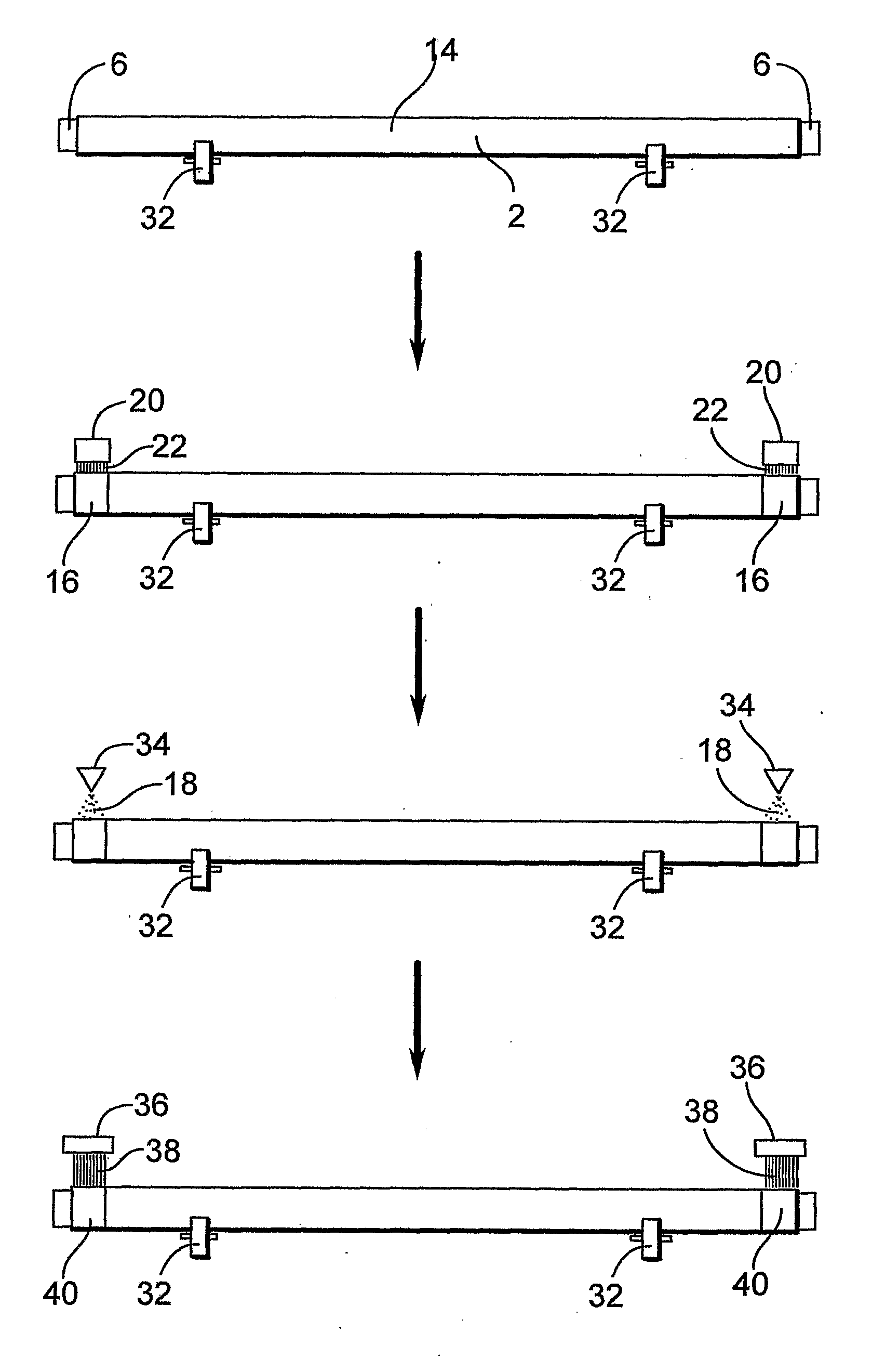
[0065]Preparation of Steel Plates Coated with a Polyolefin Coating—Steel plates (10″×4″×¼″) were washed with dish detergent, thoroughly rinsed and dried. Then the plates were thermo-pickled in an oven overnight at 325° C. to remove organic contaminants. After the plates were cooled to room temperature, they were gritblasted to SA2.5 (white metal finish) and were immediately placed in an oven to heat at 240° C. for 3 hours. The heated plates were dipped in a fusion bonded epoxy (FBE 3M 6233) fluidized powder bath for 3 seconds, followed by a light spray of the maleic anhydride grafted polyethylene adhesive 2′; (Borealis Borcoat™ ME0433). After that, black polyethylene powder (Novapol PE from Nova Chemicals) was immediately poured over the plate and allowed to sit for 10 seconds, at which point all excess powder was shaken from the plate. The coated plates were place...


PUM

PropertyMeasurementUnit
thicknessaaaaaaaaaa
thicknessaaaaaaaaaa
thicknessaaaaaaaaaa

Abstract

The present provides a bondably coated metallic member comprising a metallic member having a low surface energy polymeric coating, said low surface energy polymeric coating having been surface activated on at least a portion thereof, and having on said surface-activated portion a bondable high surface energy polymeric coating. The present invention also provides a bondably-coated metallic pipe comprising metallic pipe having a low surface energy mainline polymeric coating thereon extending over the pipe except at a bare zone adjacent each end of the pipe that is free from said main-line coating; a portion of said mainline coating adjacent each bare zone having been surface activated and having on said surface activated portion a bondable high surface energy polymeric coating.

Description

FIELD OF INVENTION[0001]The present invention relates to the preparation of polymeric coated metallic substrates, and in particular polymeric coated metallic substrates having high energy surfaces.BACKGROUND[0002]Layers of low surface energy polymers are often used as protective coatings on metal members against corrosion and against ingress of moisture. For example, polyethylene and polypropylene are commonly included in steel pipe coatings.[0003]However, the difficulty in forming a bond to such low surface energy coatings may give rise to problems in use. For example, when pipes intended to be welded together to form pipeline are coated, a short section at either end of the pipe must be left bare (the so-called “cut-back”) so that the pipes can be welded together in the field to form a pipeline. After welding, the bare sections and the weld joint must be coated with a suitable anti-corrosion coating (field joint coating) whose performance is expected to equal or exceed that of the...

Claims


Application Information

Patent Timeline
Patent Type & Authority Applications(United States)
IPC IPC(8): B32B1/08B05D5/00B05D3/04B05D3/06B05D3/08B05D3/10B05D3/12
CPCB05D3/066B05D3/067B05D3/08B05D3/105B05D3/144B05D7/146Y10T428/139B05D7/54B05D7/58F16L13/0272F16L47/24Y10T428/1379B05D7/148
Inventor LAM, CATHERINEPOTTER, DAVID K.STEELE, ROBERT E.
Owner SHAWCOR LTD
Why Eureka
Try Eureka