Turbo Charger

a technology of turbocharger and charger body, which is applied in the direction of engine control, dynamo-electric machines, tidal stream/damless hydropower, etc., can solve the problems of thermal problems and considerable repair effort of such constructions, and achieve the effect of reducing the possibility of damage, avoiding trouble, and simple construction

Active Publication Date: 2008-11-27
LINDENMAIER +1
View PDF19 Cites 16 Cited by
  • Summary
  • Abstract
  • Description
  • Claims
  • Application Information

AI Technical Summary

Benefits of technology

[0003]The present invention relates to a turbocharger which supplies precisely the correct quantity of fresh air with the smallest possible delay, and which furthermore is simple in its construction and is susceptible to trouble as little as possible.

Problems solved by technology

Such an arrangement would lead to thermal problems and represents a large design modification of conventional (purely mechanical) turbochargers.
Apart from the increased design effort, the repair effort with such constructions is considerable.

Method used


Image

  • Turbo Charger
  • Turbo Charger
  • Turbo Charger

Examples


first embodiment

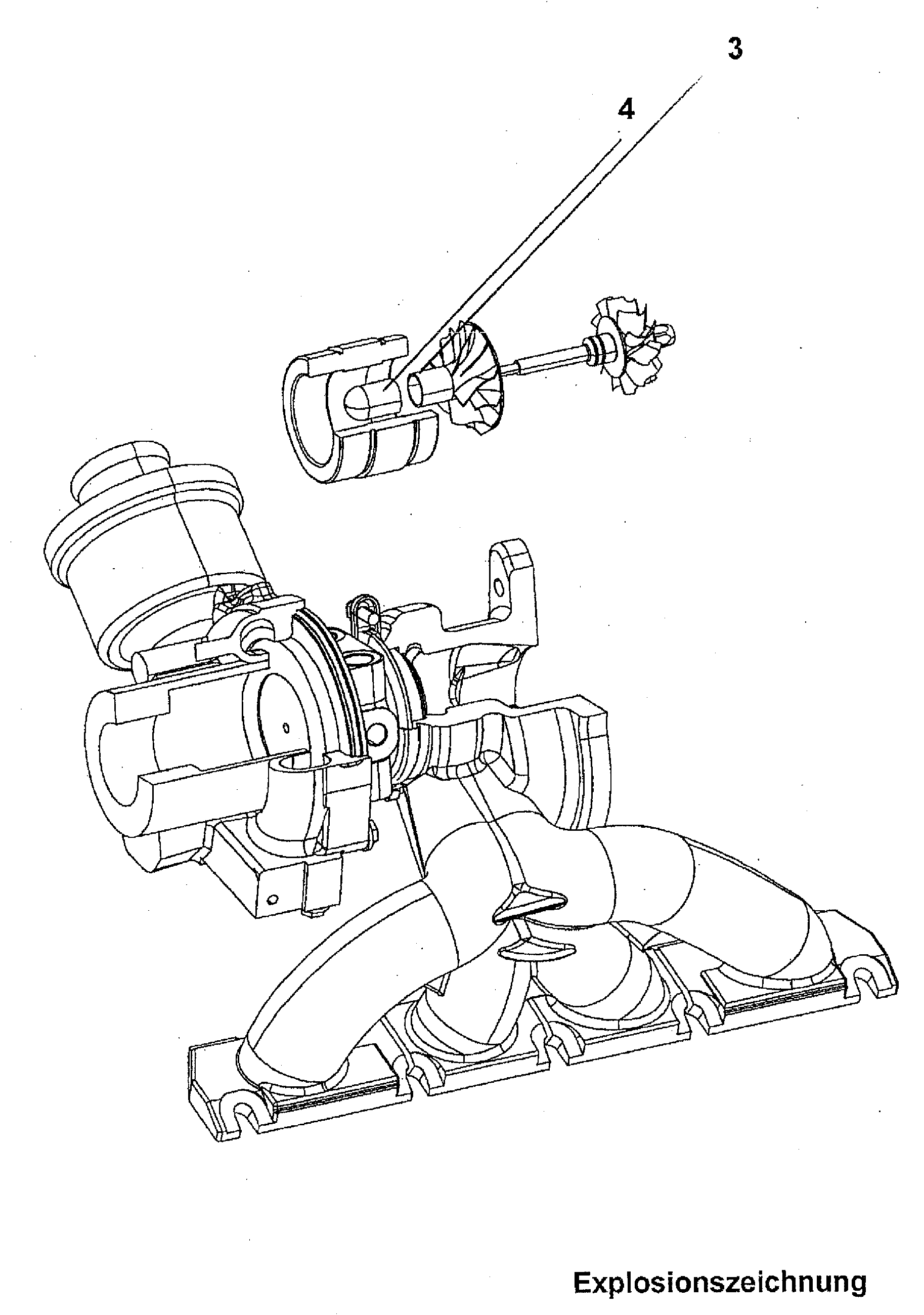
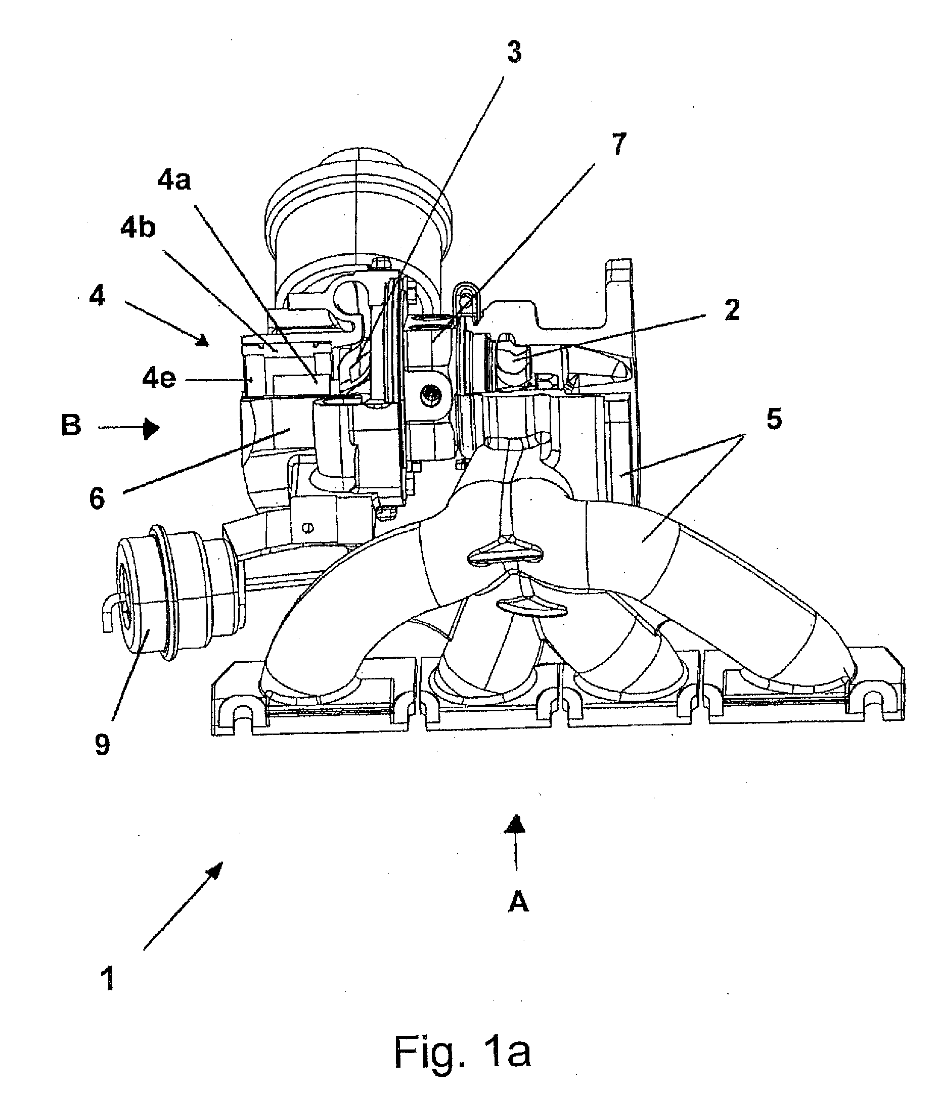
[0037]The basics of the present invention are to be shown hereinafter by way of the first embodiment according to FIGS. 1a to 1d.

[0038]FIGS. 1a to 1d show an electrically modified mechanical turbocharger 1 which may be coupled to a turbine housing 5 on an internal combustion engine. After the combustion, the exhaust gas is collected by way of the exhaust gas fans shown in FIG. 1a and is used for driving a turbine wheel 2. The turbine wheel 2 is surrounded by the turbine housing 5 and is essentially deduced from a conventional mechanical turbocharger. A bearing housing 7 connects to the turbine housing 5, and then a compressor housing 6. A compressor wheel 6 is attached in this compressor housing 6, and compresses the air fed through an inlet opening (this inlet opening is in particular easily seen in FIG. 1c) and leads it to the combustion space of the internal combustion engine in a manner which is not shown here. The compressor wheel 3 on the left side in FIG. 1a shows a continua...

second embodiment

[0049]FIGS. 2a and 2b show the invention. Here, the stator is represented in a somewhat different manner, specifically in the direct vicinity of the rotor (with a relatively small rotor gap), and the inlet air opening to the turbine wheel 3 runs radially outside the stator 4b′. The electrical feed to the stator is effected by way of webs which are provided in the gap space of the inlet air opening.

third embodiment

[0050]A third embodiment is shown in the FIGS. 3a and 3b. Here, the rotor magnet 4 has been partially integrated into the compressor wheel 3 on manufacture. The stator forms the inner contour of the compressor housing. It has a Hall-probe, with whose help the rotor rotational speed may be continuously determined.

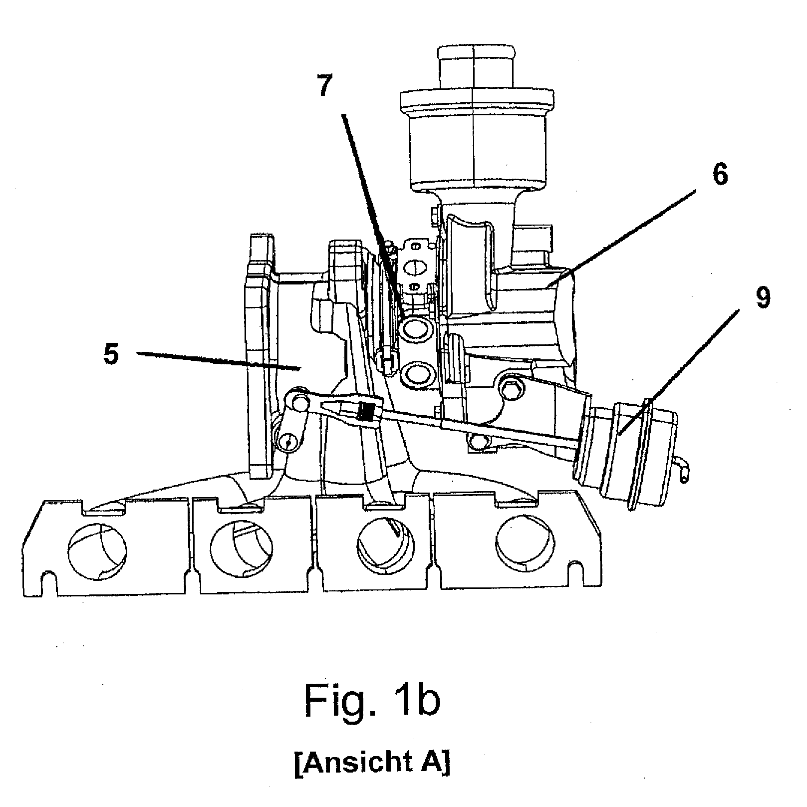
[0051]The electric motor may be operated in motor operation (for accelerating and avoiding a “turbolag”) as well as in generator operation (for recovering energy). If the charging pressure (in the turbine housing) reaches a certain nominal value, then additional energy is produced by way of using a converter capable of return feed. Ideally, one may do away with a wastegate / pressure dos for blowing out excess exhaust gas pressure, as is represented in FIG. 1b, numeral 9, by way of this energetic conversion of the braking energy in generator operation.


PUM


Abstract

A turbocharger includes a turbine wheel, a compressor wheel connected thereto, an electric motor situated on the side of the compressor wheel which is distant to the turbine wheel, and a rotor connected to the compressor wheel in a rotationally fixed manner and designed in a freely projecting manner. A drive system for motor vehicles includes a turbocharger. The turbocharger is characterised by a very spontaneous response behaviour, as well as the possibility for energy recovery.

Description

FIELD OF INVENTION[0001]The present invention relates to a turbocharger, as well as to a drive system which contains such a turbocharger.BACKGROUND INFORMATION[0002]Internal combustion engines with turbochargers are basically known in the motor vehicle sector. Typically, an exhaust gas flow out of the combustion engine is used to drive a turbine wheel. This turbine wheel is for example coupled via a shaft to a compressor wheel which ensures a compression of supplied fresh air in the combustion space. Such a precompression or “charging” leads to an increased engine power or increased torque compared to conventional internal combustion engines. However, with internal combustion engines charged in such a manner, there exists the problem of the so-called “turbolag”, which in particular occurs on running up and accelerating from low rotational speeds of the vehicle, thus when the internal combustion engine is to be rapidly accelerated into regions of increased power. This is due to the f...

Claims


Application Information

Patent Timeline
Patent Type & Authority Applications(United States)
IPC IPC(8): F02B37/04F04D25/04F04D25/06
CPCF01D5/025F01D25/16F01N13/107F02B37/025F02B37/10F02B39/10F03B17/061F04D13/0646F04D25/0606F05B2220/40F05B2220/706F05B2220/70642F05B2220/7068F05B2270/304H02K5/128H02K7/14H02K7/1823H02K9/06Y02E10/28Y02E20/14Y02T10/144F05D2270/304F05D2220/7642F05D2220/40F05D2220/76F05D2220/768F04D25/024Y02E10/30Y02T10/12Y02E10/20
Inventor GODEKE, HOLGERLOFFLER, RUDOLFHEBER, RALFBISCHOF, THOMASMAIER, SANDRAKAMPFER, OLIVER
Owner LINDENMAIER
Why Eureka
Try Eureka